Idling speed and nozzle device for wind tunnel and its control method

A spout and idle speed technology, applied in the field of wind tunnel, can solve the problems of large labor of spout profile block, influence wind tunnel test results, lack of a better solution, etc., and achieve compact structure, simple structure and accurate profile. Effect

Active Publication Date: 2020-09-22
TAKASAGO CONSTRUCTORS ENGINEERS (BEIJING) CO LTD +1
View PDF6 Cites 0 Cited by
  • Summary
  • Abstract
  • Description
  • Claims
  • Application Information

AI Technical Summary

Problems solved by technology

[0005] Manual replacement of the spout block is labor-intensive and inefficient, and a spreader needs to be erected in the workshop
If a screw push rod is used to push the flex plate to produce a predetermined profile, the profile will inevitably have certain errors, which will further affect the wind tunnel test results
[0006] For the above problems, there is currently no good solution

Method used


Image

  • Idling speed and nozzle device for wind tunnel and its control method
  • Idling speed and nozzle device for wind tunnel and its control method
  • Idling speed and nozzle device for wind tunnel and its control method

Examples


Embodiment Construction

[0029] Embodiments of an idle speed and nozzle device for a wind tunnel and a control method thereof according to the present invention will be described below with reference to the accompanying drawings. Those skilled in the art would recognize that the described embodiments can be modified in various ways or combinations thereof without departing from the spirit and scope of the invention. Accordingly, the drawings and description are illustrative in nature and not intended to limit the scope of the claims. Also, in this specification, the drawings are not drawn to scale, and like reference numerals denote like parts.

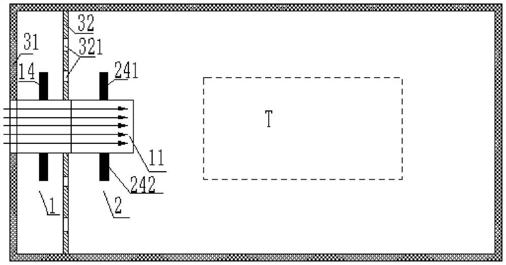
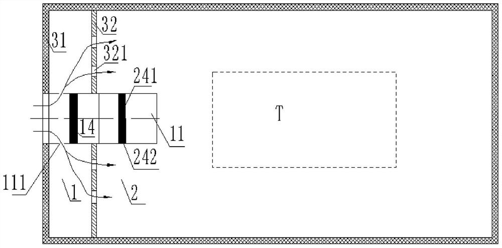
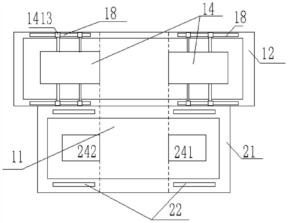
[0030] figure 1 with figure 2 It is a plan view of the airflow direction of the idle speed and nozzle device for a wind tunnel according to the embodiment of the present invention. Combine first figure 1 , figure 2 To illustrate the idle speed and the direction of the airflow in the nozzle device. Such as figure 1 , image 3 As shown, the wind tunne...


PUM


Abstract

Wind tunnel idle speed and nozzle device and its control method, the device includes an idle speed mechanism and a nozzle mechanism, the main channel penetrates the idle speed mechanism and the nozzle mechanism in turn, the idle speed mechanism includes an idle speed door body and an idle speed drive assembly, and the two idle speed door bodies are listed in On both sides of the main channel, the idle drive assembly drives the idle door body to move relatively to fit, and the main channel is closed, or the idle drive assembly drives the idle door body to move oppositely until the main channel is fully opened, and the airflow flows through the main channel; the nozzle mechanism includes The spout module and the spout drive assembly, the two spout modules are arranged on both sides of the main channel, and the spout drive assembly drives the spout modules to move relative to each other to form a small spout, or the spout drive assembly drives the spout modules to move opposite to the main channel Opens fully to create a large spout. The invention realizes free switching between large and small nozzles, and the idle speed mechanism has a compact structure, and the driving mode of the idle speed door body is simple, accurate and efficient.

Description

technical field [0001] The invention relates to the field of wind tunnel technology, in particular to an idle speed and nozzle device for a wind tunnel and a control method thereof. Background technique [0002] The wind tunnel is a major testing facility for the development of rail transit vehicles. It conducts tests and assessments on the performance of the entire vehicle through artificially created various climatic conditions and simulated vehicle operating conditions. Wind tunnels usually contain an idle mechanism and a nozzle mechanism. [0003] The idle speed mechanism is used to simulate the natural conditions of the vehicle at idle speed. The idle speed mechanism needs to block the flow channel when simulating the idle speed condition, and at the same time guide the airflow to the idle speed wall area on both sides of the flow channel. Vent window exhaust. The idle mechanism of some environmental wind tunnels adopts the structure of rolling shutters to block the f...

Claims


Application Information

Patent Timeline
Patent Type & Authority Patents(China)
IPC IPC(8): G05D7/06G01M9/04G01M17/08
CPCG05D7/0635G01M9/04G01M17/08Y02T30/00
Inventor 严瑞赵旭飞胡向焱孙铁斌原田明刘怀印施后伟李跃徐冬
Owner TAKASAGO CONSTRUCTORS ENGINEERS (BEIJING) CO LTD
Why Eureka
Try Eureka