
Shifting wheel structure for remote controller of unmanned aerial vehicle

A machine remote control and dial technology, applied in the field of drones, can solve problems such as operator fatigue and troublesome aerial photography angles, and achieve the effects of preventing wrong clamping, convenient control of drones, and convenient operation

Active Publication Date: 2018-07-06
GUANGZHOU EHANG INTELLIGENT TECH
View PDF16 Cites 0 Cited by
  • Summary
  • Abstract
  • Description
  • Claims
  • Application Information

AI Technical Summary

Problems solved by technology

The invention does not require the user to continuously maintain the position of the pulsator with fingers during the aerial photography process, and has the advantages of being able to fix the aerial photography angle of the UAV more conveniently for a long time, and solves the troublesome and troublesome problem of fixing the aerial photography angle of the UAV for a long time. Problems causing operator fatigue

Method used


Image

  • Shifting wheel structure for remote controller of unmanned aerial vehicle
  • Shifting wheel structure for remote controller of unmanned aerial vehicle
  • Shifting wheel structure for remote controller of unmanned aerial vehicle

Examples


no. 1 example

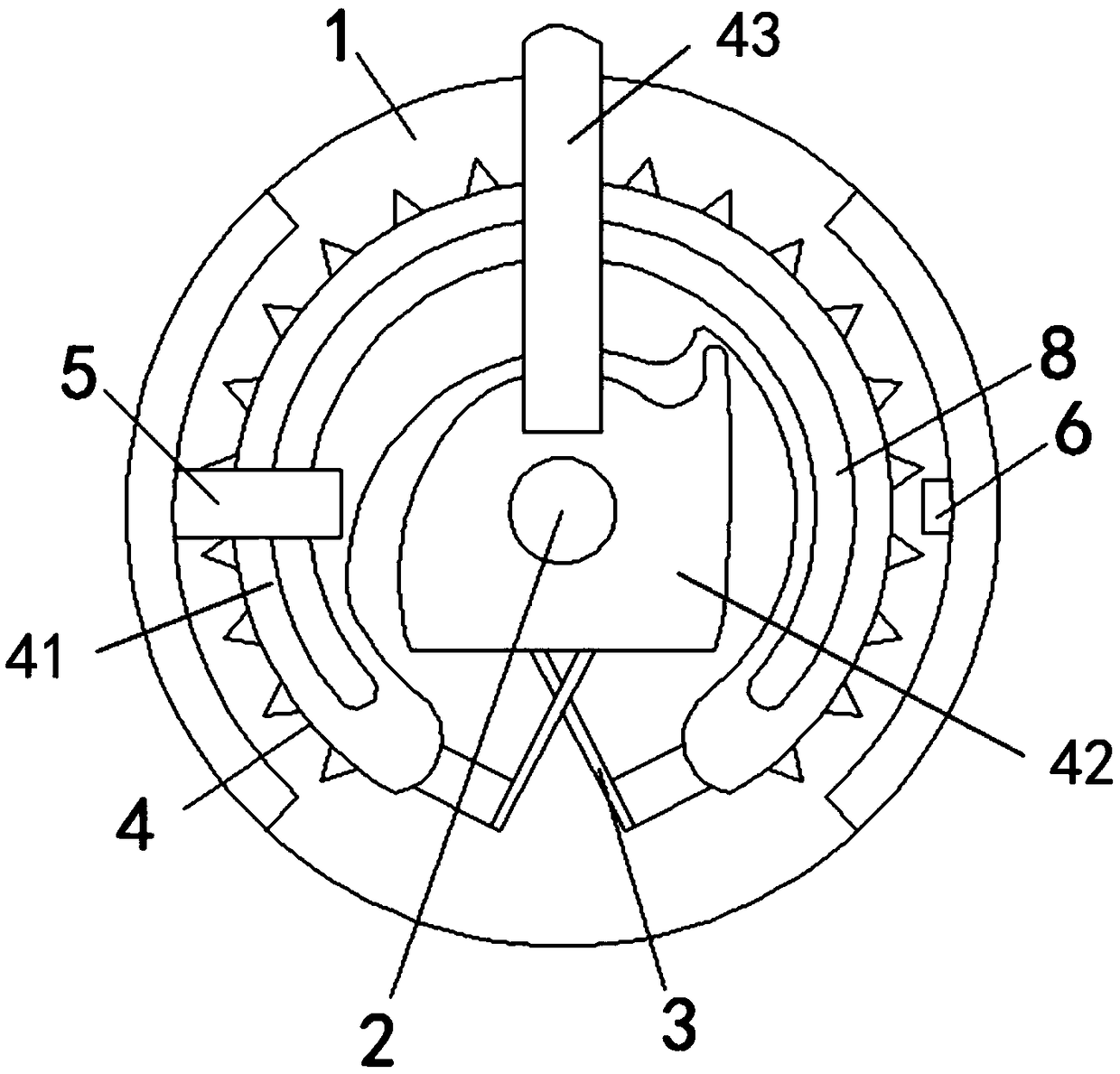
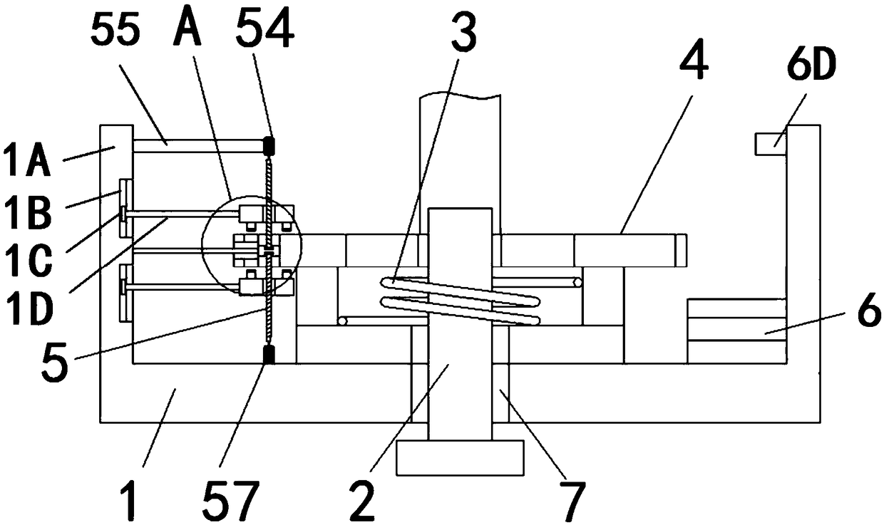
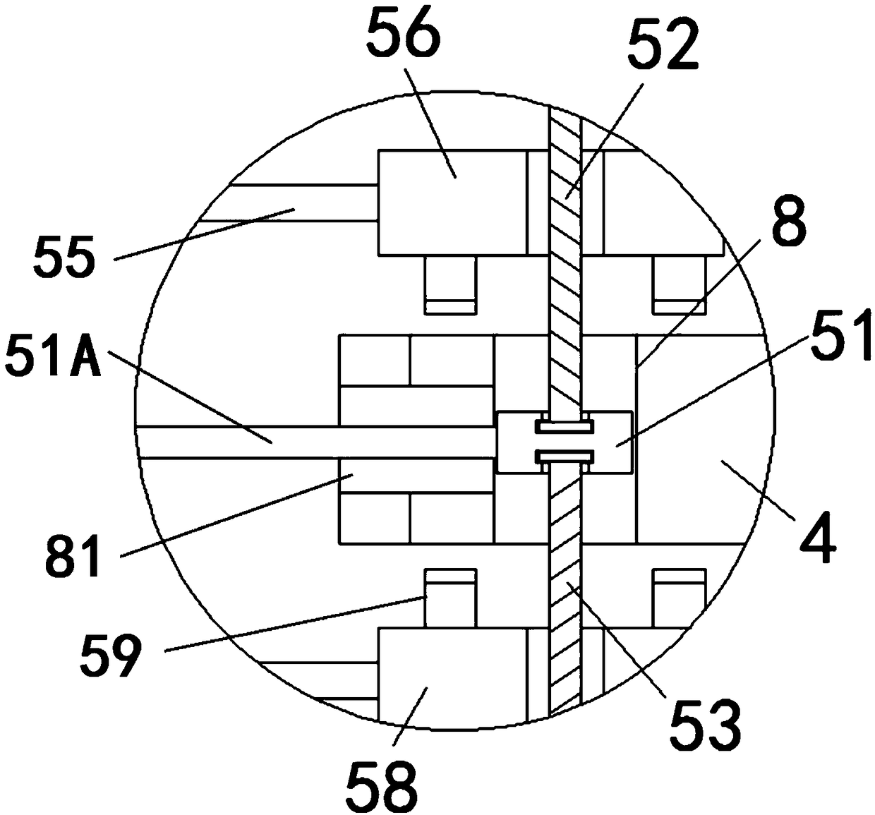
[0033] see Figure 1-3 , a dial structure for a drone remote control, including a base 1, a rotating shaft 2, an elastic reset member 3, a rotating plate 4, a fixing mechanism 5 and a control device 6, and a rotating shaft hole 7 is provided on the axis of the upper surface of the base 1 The inside of the shaft hole 7 is rotatably connected with a rotating shaft 2 , the top of the rotating shaft 2 extends above the base 1 , and an elastic return member 3 is sleeved outside the rotating shaft 2 and above the base 1 .

[0034] The outside of the rotating shaft 2 and above the elastic return member 3 is provided with a rotating plate 4. The rotating plate 4 includes an arc-shaped toothed ring 41 and a rotating clamping plate 42. The top of the inner wall of the arc-shaped toothed ring 41 is provided with a card. Slot, the rotating clamping plate 42 is located inside the arc-shaped tooth ring 41, the outer surface of the rotating clamping plate 42 and the corresponding clamping gr...

no. 2 example

[0038] refer to Figure 5-6 , as another preferred embodiment of the present invention, the fixing mechanism 5 includes a driving motor 59, the driving motor 59 drives the third screw rod 510 to rotate, and the outside of the third screw rod 510 is sleeved above the third clamping plate 511 There is a rotating shaft seat, and the rotating shaft seat is fixedly connected to the base 1 through a fixed rod to prevent the third screw rod 510 from shifting. Since the thread directions at the upper and lower ends of the third screw rod 510 are opposite, the rotation of the third screw rod 510 drives the third clamping rod. The plate 511 and the fourth clamping plate 512 move towards each other, the third clamping plate 511 and the fourth clamping plate 512 clamp the rotary plate 4, the left and right sides of the bottom surface of the third clamping plate 511 and the fourth clamping plate 512 The left and right sides of the surface are respectively fixedly connected with second clam...


PUM


Abstract

The invention relates to the technical field of unmanned aerial vehicles, and discloses a shifting wheel structure for the remote controller of an unmanned aerial vehicle. The shifting wheel structurecomprises a base, a rotating shaft, an elastic resetting piece, a rotating plate, a fixing mechanism and a control device. The fixing mechanism comprises a driving motor and a clamping mechanism. Thedriving motor is controlled by the control device to drive the clamping mechanism to clamp the rotating plate or release the clamping of the rotating plate. The control device is used for controllingto clamp the rotating plate when the time duration of the rotating plate kept at a specific position exceeds a preset time duration. According to the invention, the shifting wheel for the remote controller can be actively kept at an adjusted position till the shifting wheel is re-operated by a user. Therefore, the user no longer needs to continuously maintain the position of the shifting wheel byfingers during the aerial photography process. As a result, the aerial photography angle of the unmanned aerial vehicle can be fixed more conveniently for a long period of time. The problem that thelong-term fixation for the aerial photography angle of the unmanned aerial vehicle is very troublesome and causes the fatigue of an operator can be solved.

Description

technical field [0001] The invention relates to the technical field of unmanned aerial vehicles, in particular to a dial structure for a remote control of an unmanned aerial vehicle. Background technique [0002] Unmanned aircraft is referred to as "UAV" for short, and the English abbreviation is "UAV". It is an unmanned flight device controlled by radio remote control equipment and its own program control device. UAVs have a wide range of application scenarios: in terms of military use, UAVs can be used as reconnaissance aircraft and target aircraft; in terms of civilian use, UAVs can be combined with various industry applications to meet real rigid needs; , miniature selfies, express transportation, disaster rescue, observing wild animals, monitoring infectious diseases, surveying and mapping, news reports, power inspections, disaster relief, film and television shooting, making life romantic and other fields, greatly expanding the UAV itself. Developed countries are also...

Claims


Application Information

Patent Timeline
IPC IPC(8): G05G1/06
CPCG05G1/06
Inventor 王晓君唐哲君张宏刘剑薛鹏
Owner GUANGZHOU EHANG INTELLIGENT TECH
Learn More