
Micron-scale LED display device and manufacturing method capable of realizing light effect extraction and color conversion

A color conversion and display device technology, applied in identification devices, instruments, semiconductor devices, etc., can solve the problems of Micro-LED display pixel shrinkage, quantum dots are not easy to achieve quantum dot patterning, light interference, etc., and increase the overall thickness of the device. , Increase the cost of device fabrication, enhance the effect of light output efficiency

Active Publication Date: 2020-02-07
FUZHOU UNIV
View PDF6 Cites 2 Cited by
  • Summary
  • Abstract
  • Description
  • Claims
  • Application Information

AI Technical Summary

Problems solved by technology

However, this method is not easy to achieve quantum dot patterning by inkjet printing quantum dots, and the light is prone to interference after the blue LED excites the quantum dots. In order to optimize and high light efficiency, the printed quantum dots need to have a certain thickness, and the thickness is too thick will limit the further reduction of Micro-LED display pixels

Method used


Image

  • Micron-scale LED display device and manufacturing method capable of realizing light effect extraction and color conversion
  • Micron-scale LED display device and manufacturing method capable of realizing light effect extraction and color conversion
  • Micron-scale LED display device and manufacturing method capable of realizing light effect extraction and color conversion

Examples


Embodiment Construction

[0041] The technical solution of the present invention will be specifically described below in conjunction with the accompanying drawings.

[0042] In order to make the object, technical solution and advantages of the present invention clearer, the present invention will be further described in detail below through specific embodiments and related drawings. In the drawings, the thicknesses of layers and regions are exaggerated for clarity, but as a schematic diagram, it should not be considered as strictly reflecting the proportional relationship of geometric dimensions. Here, the referenced figures are schematic diagrams of idealized embodiments of the present invention, and embodiments of the present invention should not be construed as limited to the particular shapes of regions shown in the figures, but to include resulting shapes, such as manufacturing-induced deviations. In this embodiment, they are all represented by rectangles or circles, and the representations in the...


PUM

PropertyMeasurementUnit
lengthaaaaaaaaaa
widthaaaaaaaaaa
thicknessaaaaaaaaaa

Abstract

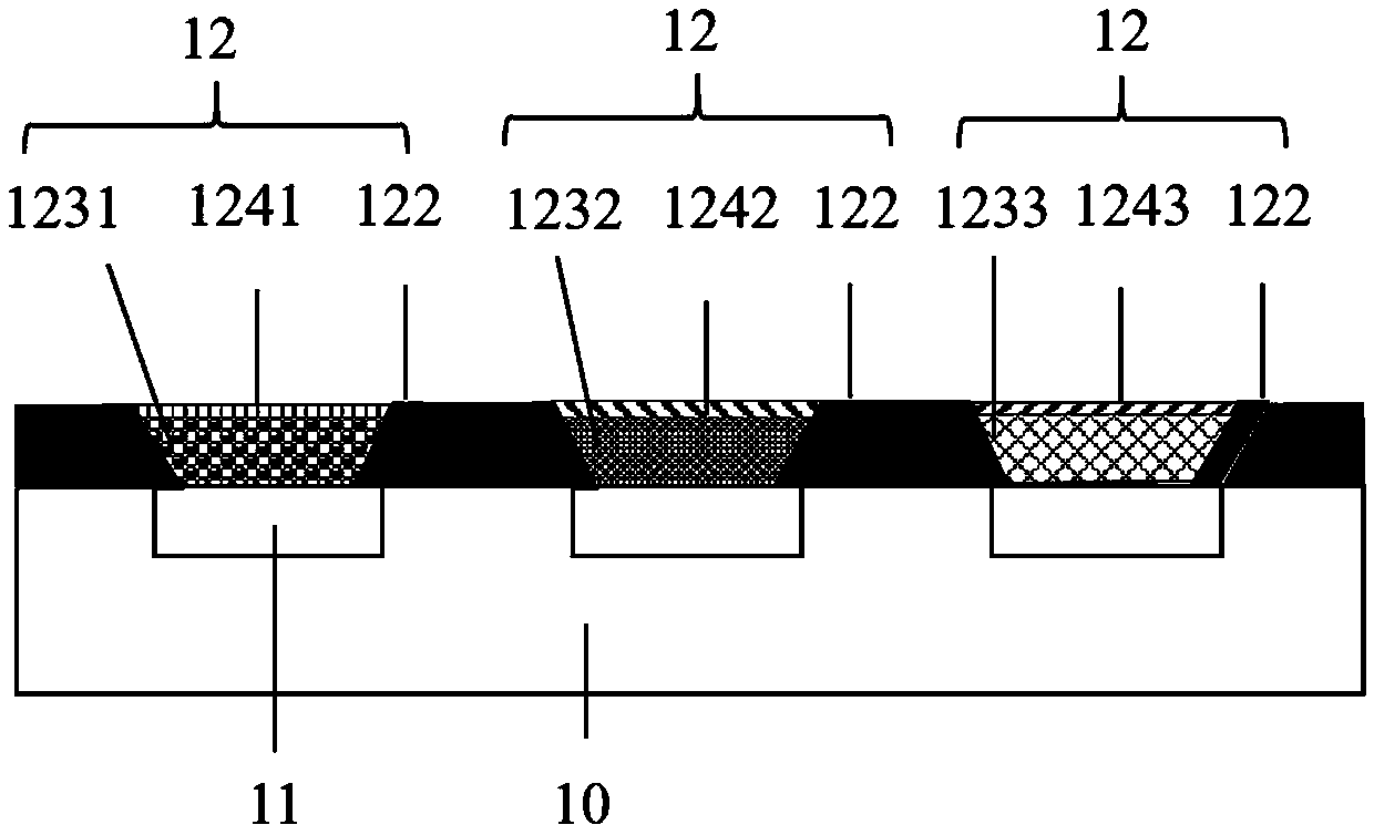
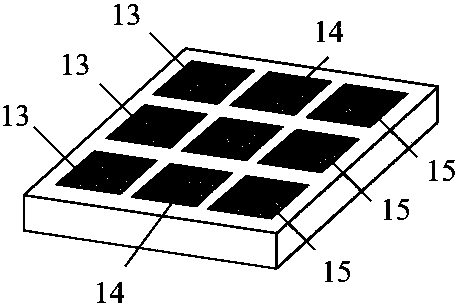
The invention relates to a micron-scale LED display device achieving light effect extraction and color conversion and a manufacturing method. The micron-scale LED display device comprises a pluralityof LED chips arranged on the surface of a substrate and distributed in an array and microstructures which are arranged on the surfaces of the LED chips and correspond to the LED chips in a one-to-onemanner; the microstructures comprise inverted-trapezoidal liquid storage grooves, and reflecting layers are arranged on the inner circumference sides of the liquid storage grooves; the microstructuresdistributed in an array and the LED chips sequentially form R units, G units and B units in the transverse direction, wherein the liquid storage grooves of the R units / the G units are each provided with a red / green quantum dot layer and a distributed Bragg reflection layer in sequence from bottom to top, and the liquid storage grooves of the B units are each sequentially provided with a transparent layer and a distributed Bragg reflection layer from bottom to top; the LED chips can emit blue light, and the blue light emitted by the LED chips is converted into red light / green light through thered quantum dot layers / the green quantum dot layers. By means of the micron-scale LED display device achieving light effect extraction and color conversion and the manufacturing method, emitting of light in the perpendicular direction can be increased; meanwhile, the intensity of the emitted light can be enhanced, and color conversion and the light extraction efficiency of micron-scale LED displaying can be effectively improved.

Description

technical field [0001] The invention relates to the field of novel semiconductor displays, in particular to a micron-scale LED display device capable of realizing light effect extraction and color conversion and a manufacturing method. Background technique [0002] Micron-scale LED refers to the miniaturization of traditional LEDs to form a micron-scale pitch LED array to achieve ultra-high-density pixel resolution. Micron-level LED display has the characteristic of self-illumination. Compared with OLED and LCD display, micron-level LED display is easier to adjust the color accurately, has a longer luminous life and higher brightness, and is more thin and light and power-saving. Micron-scale or even nano-scale LED arrays are the only display devices that can integrate drive, light emission, and signal transmission with high luminous efficiency and low power consumption, and realize ultra-large-scale integrated light-emitting units. It combines the two technical characteristi...

Claims


Application Information

Patent Timeline
Patent Type & Authority Patents(China)
IPC IPC(8): H01L25/075H01L33/46H01L33/48H01L33/50G09F9/33
CPCG09F9/33H01L25/0753H01L33/46H01L33/486H01L33/504H01L2933/0025H01L2933/0033H01L2933/0041
Inventor 张永爱张桑玲周雄图郭太良叶芸林志贤林朝福翁雅恋
Owner FUZHOU UNIV
Learn More