
Shaft run-through position sealed structure of pedestal type sliding bearing structured motor

A technology of seat type sliding bearing and sliding bearing, which is used in electrical components, electromechanical devices, electric components, etc., can solve problems such as difficulty in sealing

Pending Publication Date: 2018-07-06
JIAMUSI ELECTRIC MACHINE
View PDF3 Cites 0 Cited by
  • Summary
  • Abstract
  • Description
  • Claims
  • Application Information

AI Technical Summary

Problems solved by technology

The product is simple in structure and reasonable in design. It forms an independent cavity between the sealing cover and the seat type sliding bearing, and converts the original dynamic sealing structure into a static sealing structure. After testing, the sealing effect is good, and it solves the long-standing problem of sealing the shaft through the part. Difficult problems, greatly reducing the gas leakage of the motor cavity, saving energy, and improving product reliability and safety

Method used


Image

  • Shaft run-through position sealed structure of pedestal type sliding bearing structured motor
  • Shaft run-through position sealed structure of pedestal type sliding bearing structured motor

Examples


specific Embodiment approach

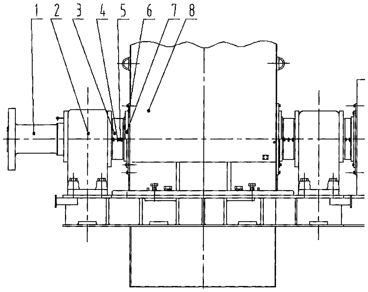
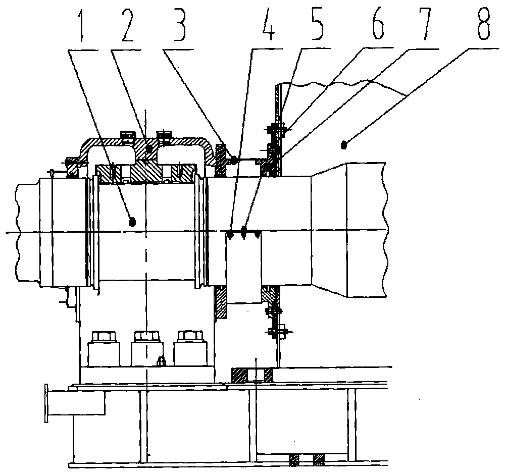
[0008] Specific embodiments: The best embodiment of the present invention will be described in detail below in conjunction with the accompanying drawings. A sealing structure at the penetration of the motor shaft with a seat type sliding bearing structure consists of: shaft 1, seat type sliding bearing 2, pressure plate 3, bolt connector 4, Gasket 5, sealing plate 6, sealing cover 7, machine base 8 constitute. The shaft 1 is installed in the machine base 8, the seat type sliding bearing 2 is installed on the shaft 1, the upper and lower pressure plates 3 are installed between the machine base 8 and the seat type sliding bearing 2 through the bolt connection 4, and the upper and lower pressure plates 3 A gasket 5 is installed between them, a sealing plate 6 is installed on the machine base 8 through bolts, and a sealing cover 7 is mounted on the sealing plate 6 .

[0009] Due to the adoption of this sealing structure, the sealing structure at the penetration of the seat type sl...


PUM


Abstract

The invention relates to a shaft run-through position sealed structure of a pedestal type sliding bearing structured motor. The shaft run-through position sealed structure consists of a shaft, a pedestal type sliding bearing, pressing plates, a bolt connecting piece, a sealing cushion, a sealing plate, a sealing cover and a machine base; the shaft is mounted in the machine base; the pedestal typesliding bearing is mounted on the shaft; the upper and lower pressing plates are mounted between the machine base and the pedestal type sliding bearing through the bolt connecting piece; the sealing cushion is mounted between the upper and lower pressing plates; the sealing plate is mounted on the machine base through a bolt; and the sealing cover is mounted on the sealing plate. The shaft run-through position sealed structure is simple in structure and reasonable in design; and by forming an independent cavity between the sealing cover and the pedestal type sliding bearing, the original dynamic sealing structure is converted into a static sealing structure, and a good sealing effect is proved by tests, so that the problem of difficulty in shaft run-through position sealing for a long termis solved, the gas leakage amount of the motor cavity is greatly reduced, energy is saved, and product reliability and safety are improved.

Description

technical field [0001] The invention relates to a sealing structure at the penetration part of a motor shaft with a seat type sliding bearing structure. Background technique [0002] At present, the explosion-proof type commonly used in large-scale explosion-proof motors in China is increased safety type, positive pressure shell type, which has extremely high requirements on the sealing of the motor. The seals of most parts of the motor are static seals, that is, the seals of the two stationary parts. Such as machine base and cooler, machine base and cover plate, etc., the sealing of such stationary parts is relatively easy, but the key to affecting the leakage of the motor is the dynamic seal at the shaft penetration, that is, the seal between the stationary part and the rotating part , the shaft penetration of the traditional seat-type sliding bearing structure motor is the seal cover and the shaft adopts a mechanical seal, and the gap between the shaft and the seal cover ...

Claims


Application Information

Patent Timeline
Patent Type & Authority Applications(China)
IPC IPC(8): H02K7/00H02K5/124
CPCH02K5/124H02K7/003
Inventor 王晓文王殿友历锐程征员马文博姜巍李方华乔丽娜唐庆军葛新乐冯龙王洪彬苏国霞张爽赵倩
Owner JIAMUSI ELECTRIC MACHINE
Learn More