Gas supplying pipeline

A technology of air supply pipes and ventilation pipes, applied in respiratory protection devices, fire rescue, life-saving equipment, etc., can solve problems such as the inability to continuously inhale fresh air, the burden on the escape personnel, and the inconvenience of using the air outlet.

Inactive Publication Date: 2018-07-10
吴超然
View PDF0 Cites 2 Cited by
  • Summary
  • Abstract
  • Description
  • Claims
  • Application Information

AI Technical Summary

Problems solved by technology

Such a technical measure has the disadvantage of being inconvenient to use the air outlet, and cannot continuously inhale fresh air

Method used


Image

  • Gas supplying pipeline
  • Gas supplying pipeline
  • Gas supplying pipeline

Examples


Embodiment Construction

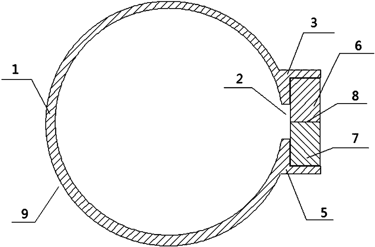
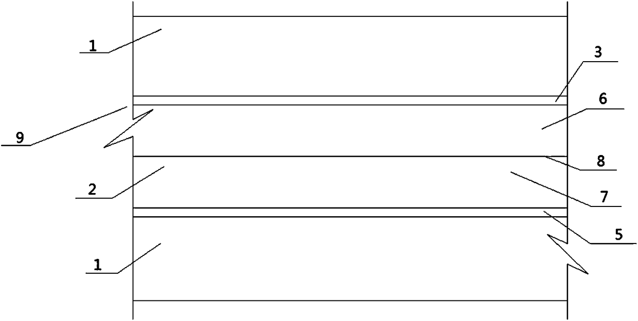
[0043] Such as figure 1 said, figure 1 It is a cross-sectional view of the air supply pipeline 9 of the first embodiment of the present application. The pipe wall 1 of the air supply pipeline 9 of the first embodiment of the application is provided with a linear opening 2 along the hole direction of the air supply pipeline 9. The above opening 2 Through the pipe wall 1, the pipe wall 1 on one side of the opening 2 is provided with a strip-shaped L-shaped groove 3 for accommodating the sealing strip I6, and the pipe wall 1 on the other side of the above-mentioned opening 2 is provided with a strip for accommodating the sealing strip II7. Shaped L-shaped groove 5, L-shaped groove 3 is connected with sealing strip I6, L-shaped groove 5 is connected with sealing strip II7, and sealing strip I6 and sealing strip II7 are relatively close together to play the role of sealing opening 2. Insert the gap 8 between the sealing strip I6 and the sealing strip II7 directly or through the co...


PUM


Abstract

Provided is a gas supplying pipeline. The pipe wall of the gas supplying pipeline is provided with a linear opening in the hole direction of the gas supplying pipeline; the pipe wall is fully or partially made of an elastic material; and according to the opening, a plurality of persons can get close to the opening to directly inhale with the mouths at the same time, or gas passing pipes are used and are inserted into the opening for inhaling.

Description

technical field [0001] The present application relates to a gas supply pipeline. Background technique [0002] There are many combustible decorations, chemical fiber carpets and furniture filled with foam plastics in modern buildings. These combustibles will produce a lot of toxic smoke and heat during combustion, and consume a lot of oxygen. In building fires, smoke is the main cause of preventing people from escaping and causing the death of trapped people. According to the statistics of the causes of casualties in fires in the UK, the death toll due to suffocation due to carbon monoxide poisoning or other toxic smoke generally accounts for 40% to 50% of the total death toll, and among the people who were burned to death, most of them were poisoned first. Burned to death after asphyxiation. When a fire breaks out, because combustion consumes a lot of oxygen, the oxygen concentration in the air drops significantly. If people stay in this hypoxic environment for a long tim...

Claims


Application Information

Patent Timeline
IPC IPC(8): A62B7/00
CPCA62B7/00
Inventor 吴超然
Owner 吴超然
Why Eureka
Try Eureka