A bracket pipe connector
A technology of connectors and bracket pipes, which is applied in the connection of rods, connecting components, mechanical equipment, etc., can solve the problems of not being able to realize the stable connection of pipe fittings, and cannot ensure that the joints of pipe fittings will not be squeezed and deformed, so as to avoid deformation and facilitate The effect of changing and ensuring a stable connection
- Summary
- Abstract
- Description
- Claims
- Application Information
AI Technical Summary
Problems solved by technology
Method used
Image

Examples
specific Embodiment approach 1
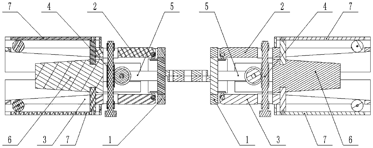
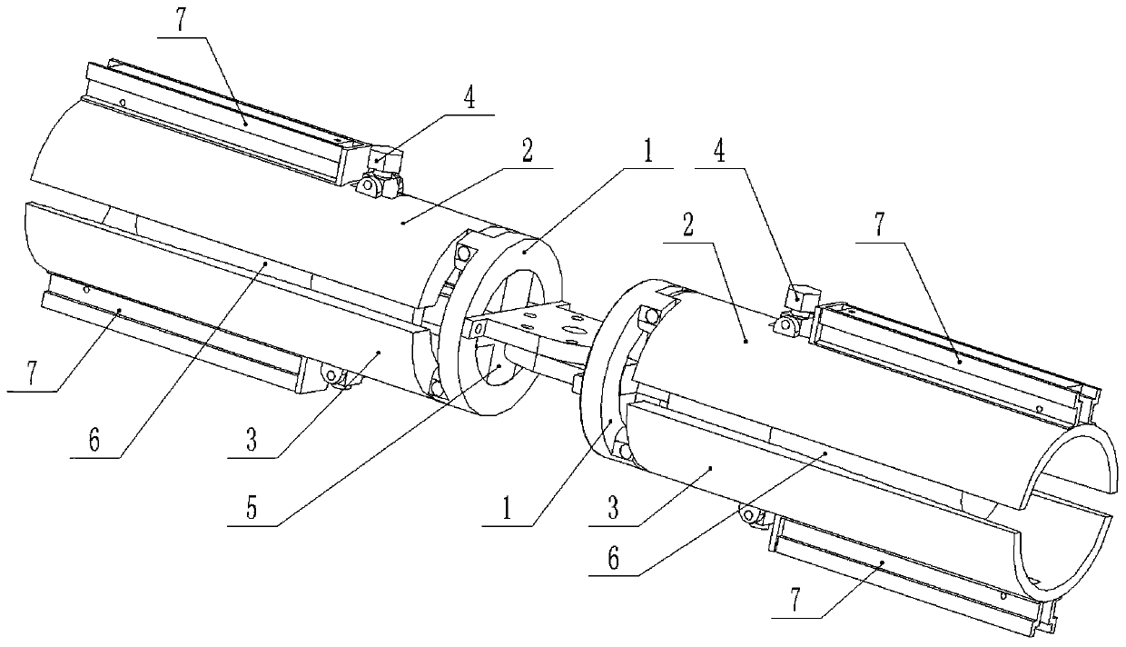
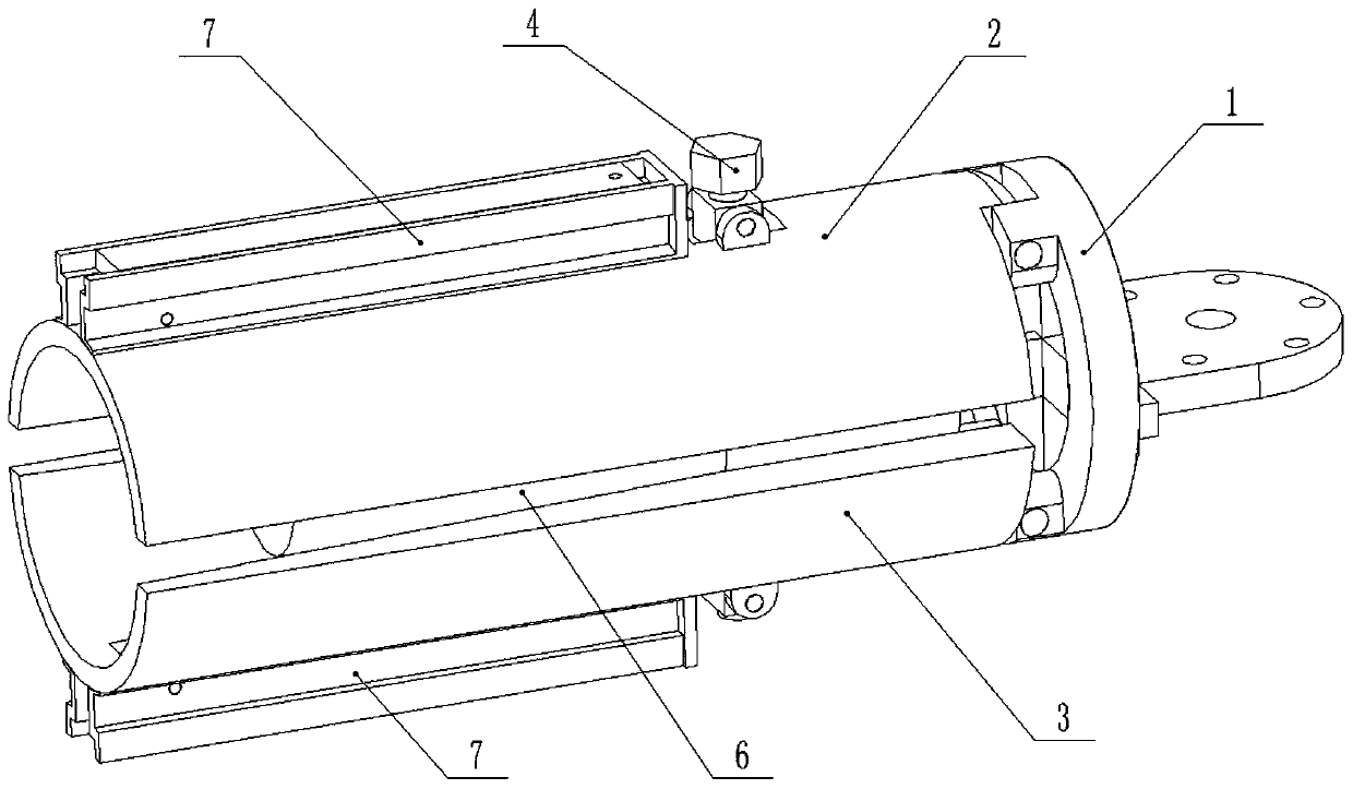
[0033] Combine below Figure 1-14 Describe this embodiment, a bracket pipe connector, including a fixed frame 1, an arc-shaped outer compression sleeve I2, an arc-shaped outer compression sleeve II3, a screw worm assembly 4, a worm gear assembly 5, and a pipe inner compression column 6. The outer end of the fixed frame 1 is hingedly connected to the arc-shaped outer compression sleeve I2 and the arc-shaped outer compression sleeve II3, and one end of the screw and worm assembly 4 is rotatably connected to the arc-shaped outer compression sleeve I2, and the screw and worm assembly The other end of 4 is connected to the arc-shaped outer compression sleeve II3 through thread fitting, the worm gear assembly 5 is fixedly connected to the fixed frame 1, the screw worm assembly 4 and the worm gear assembly 5 are meshed and connected through the worm gear, and the inside of the tube The compression column 6 is slidably connected between the arc-shaped outer compression sleeve I2 and t...
specific Embodiment approach 2
[0035] Combine below Figure 1-14This embodiment will be described. This embodiment will further describe the first embodiment. The fixed frame 1 includes a fixed ring 1-1 and a horizontal flange 1-2, and the horizontal flange 1-2 is fixedly connected to the One end of the fixed ring 1-1, the arc-shaped outer compression sleeve I2 and the arc-shaped outer compression sleeve II3 are hingedly connected to the other end of the fixed ring 1-1, and the fixed frame 1 is provided with two, two Two horizontal flanges 1-2 are fixedly connected by bolts; two bracket pipe connectors are connected by horizontal flanges 1-2, so that the angle transformation between the two connected pipes can be realized, and the two pipes can be connected The pieces are connected together, and the angle adjustment between the two pieces can be realized.
specific Embodiment approach 3
[0037] Combine below Figure 1-14 Describe this embodiment, this embodiment will further explain the first embodiment, the arc-shaped outer compression sleeve I2 is provided with a screw groove I2-1, a connecting column slide groove I2-2 and a screw connector I2-3, the The screw connector I2-3 is hingedly connected in the screw groove I2-1, the screw connector I2-3 is provided with a circular through hole, and the inner diameter of the outer end of the arc-shaped outer compression sleeve I2 is larger than the inner diameter of the inner end; When the screw and worm assembly 4 is fastened, the screw connecting piece I2-3 rotates slightly.
PUM
 Abstract
Description
Claims
Application Information
 - R&D
- Intellectual Property
- Life Sciences
- Materials
- Tech Scout
- Unparalleled Data Quality
- Higher Quality Content
- 60% Fewer Hallucinations
Browse by: Latest US Patents, China's latest patents, Technical Efficacy Thesaurus, Application Domain, Technology Topic, Popular Technical Reports.
© 2025 PatSnap. All rights reserved.Legal|Privacy policy|Modern Slavery Act Transparency Statement|Sitemap|About US| Contact US: help@patsnap.com