Grain elevator capable of ventilating determined position

A technology to determine the location and granary, which is applied in the field of granaries that can ventilate the determined location, can solve the problems of grain rot and poor ventilation, and achieve the effect of avoiding unventilated rot and facilitating fixed-point ventilation

Inactive Publication Date: 2018-07-13
河南创卓仓储科技股份有限公司
View PDF1 Cites 3 Cited by
  • Summary
  • Abstract
  • Description
  • Claims
  • Application Information

AI Technical Summary

Problems solved by technology

[0005] The invention overcomes the deficiencies of the prior art, provides a granary that can effectively ventilate the grain at a certain location, and solves the problem of grain rot caused by poor ventilation in the existing granary

Method used


Image

  • Grain elevator capable of ventilating determined position
  • Grain elevator capable of ventilating determined position

Examples


Embodiment 1

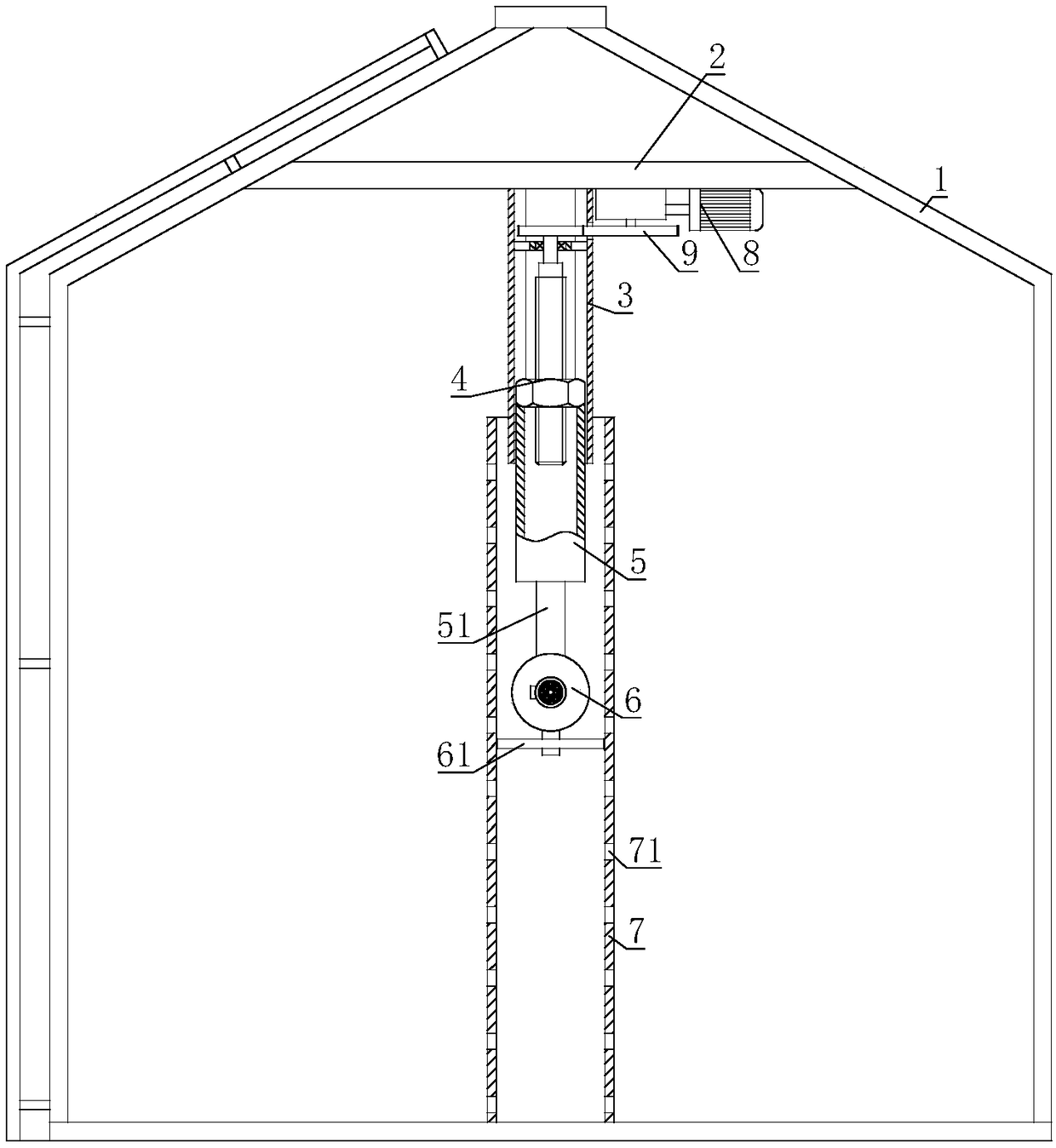
[0024] The granary that can ventilate a certain position includes a granary main body 1; a horizontal plate 2 is connected to the top of the granary main body 1, and a casing 3 is fixed on the horizontal plate 2, and a lead screw and nut mechanism 4 is connected inside the casing 3, and the screw and nut mechanism 4 is connected inside the casing 3. The other end of the lever nut mechanism 4 is connected with a lift pipe 5, and the other end of the lift pipe 5 is connected with a lift rod 51, and the other end of the lift rod 51 is connected with a blower 6, and a ventilation pipe 7 is installed in the main body of the granary 1. A number of ventilation holes 71 are provided, and the blower 6 and the lifting rod 51 are sleeved in the ventilation pipe 7; the horizontal plate 2 is also equipped with a driving mechanism 8, and the output shaft of the driving mechanism 8 is connected with a transmission mechanism 9, and the output end of the transmission mechanism 9 is connected to ...

Embodiment 2

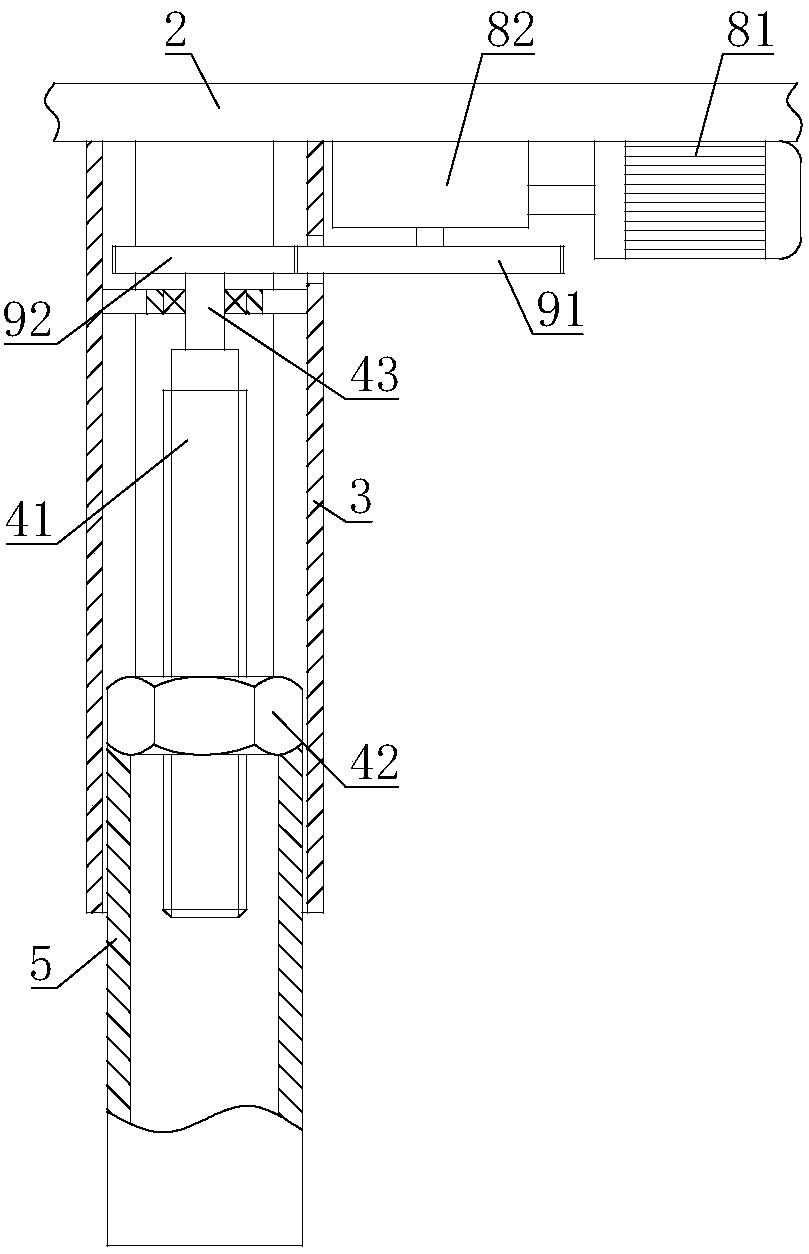
[0027] On the basis of Embodiment 1, the lead screw nut mechanism 4 includes a lead screw 41, the lead screw 41 is sleeved in the casing 3, the lead screw 41 is threadedly connected with a nut 42, and the lifting tube 5 is fixed on the nut 42; One end of bar 41 is connected with connecting shaft 43, and connecting shaft 43 is connected in the sleeve pipe 3 by bearing, and the other end of connecting shaft 43 is connected with transmission mechanism 9; The inner ring shape of the section of sleeve pipe 3 is polygonal.

[0028] When the transmission mechanism 9 drives the screw 41 to rotate, the rotation of the nut 42 is restricted by the sleeve 3, and the nut 42 rises and falls linearly under the drive of the screw 41, and the lifting tube 5 and the lifting rod 515 rise and fall under the promotion of the nut 42, so that the blower 6 Can be moved to a certain location. The screw nut mechanism 4 has a definite transmission ratio, and the moving distance of the blower 6 is propor...

Embodiment 3

[0030] On the basis of Embodiment 1 or Embodiment 2, the drive mechanism 8 includes a motor 81, the output shaft of the motor 81 is connected with a speed reducer 82, the motor 81 and the speed reducer 82 are all installed on the horizontal plate 2, and the speed reducer 82 The output shaft is connected with the input end of the transmission mechanism 9 .

[0031] After the motor 81 starts, the motor 81 drives the speed reducer 82 to act, and the speed reducer 82 transmits the power to the transmission mechanism 9, so the transmission mechanism 9 can drive the lead screw nut mechanism 4 to act. The present invention is driven by motor 81, then the start-up time of motor 81 determines the lifting height of blower 6, and the turning direction of motor 81 determines the moving direction of blower 6, easy to control, simple to operate.


PUM


Abstract

The invention relates to the field of grain storage equipment, in particular to a grain elevator capable of ventilating the determined position. According to the technical scheme, the grain elevator capable of ventilating the determined position comprises a grain elevator body; a transverse plate is connected to the top of the grain elevator body, a sleeve is fixedly arranged on the transverse plate, a lead screw and nut mechanism is connected to the sleeve, a lifting pipe is connected to the other end of the lead screw and nut mechanism, a lifting rod is connected to the other end of the lifting pipe, an air blower is connected to the other end of the lifting rod, a vent pipe is installed inside the grain elevator body, a plurality of vent holes are formed in the vent pipe, and the air blower and the lifting rod are sleeved with the vent pipe; a driving mechanism is installed on the transverse plate, an output shaft of the driving mechanism is connected with a transmission mechanism,and the output end of the transmission mechanism is connected with the lead screw and nut mechanism. The grain elevator capable of ventilating the determined position can effectively ventilate grains,and the problem that grains are corroded due to the fact that ventilation of an existing grain elevator is not smooth is solved.

Description

technical field [0001] The invention relates to the field of grain storage equipment, in particular to a granary capable of ventilating certain positions. Background technique [0002] A granary is a special building for storing grain. my country is a large agricultural country with a long history of grain production and storage. According to a large number of cultural relics and historical research unearthed in China in the past fifty years, China's primitive agriculture was enlightened in the late Paleolithic Age and developed in the new era. The storage of grain is the continuation of agricultural cultivation, and storage technology develops along with the development of agriculture. After entering the new era, with the development of primitive agriculture, agricultural production has formed a certain scale, and grain surplus has gradually developed from grain processing to storage. Classification of granary: 1. Classification according to the grain storage method in th...

Claims


Application Information

Patent Timeline
Patent Type & Authority Applications(China)
IPC IPC(8): A01F25/14A01F25/22
CPCA01F25/14A01F25/22
Inventor 李凯
Owner 河南创卓仓储科技股份有限公司
Why Eureka
Try Eureka