
A life-saving device for high-rise buildings

A life-saving device and high-rise building technology, applied in building rescue, life-saving equipment, etc., can solve the problems of low fire extinguishing efficiency, delay of the golden time of disaster relief, difficulty, etc., and achieve good escape effect

Inactive Publication Date: 2020-06-23
LUSHAN COLLEGE OF GUANGXI UNIV OF SCI & TECH
View PDF6 Cites 0 Cited by
  • Summary
  • Abstract
  • Description
  • Claims
  • Application Information

AI Technical Summary

Problems solved by technology

Secondly, for the self-falling escape system, it is difficult for untrained people to tie the escape rope by themselves, and then jump out of the window or balcony tens of meters above the ground, or even hundreds of meters to escape.
[0008] Second, the existing high-rise building escape device only considers the problem of personnel evacuation, but fails to consider the fire extinguishing problem of high-rise buildings
First of all, the lifting height of the fire-fighting aerial ladder vehicle is limited, and the fire-fighting aerial ladder vehicle is helpless for high-rise building fires exceeding the lifting height
Secondly, a fire-fighting ladder truck can only lift one fire-fighting water gun, and the fire-fighting efficiency is low; when it is used for people to escape, the fire-fighting ladder truck with hydraulic working principle has a slow lifting speed and the efficiency of personnel evacuation is not high enough.
[0010] Third, high-rise buildings are generally concentrated in prosperous areas, and the large fire-fighting aerial ladder vehicles often cannot reach the fire scene in the first time, which delays the prime time for disaster relief

Method used


Image

  • A life-saving device for high-rise buildings
  • A life-saving device for high-rise buildings
  • A life-saving device for high-rise buildings

Examples


Embodiment Construction

[0035] The preferred embodiments of the present invention will be described in detail below in conjunction with the accompanying drawings, so that the advantages and features of the present invention can be more easily understood by those skilled in the art, so as to define the protection scope of the present invention more clearly.

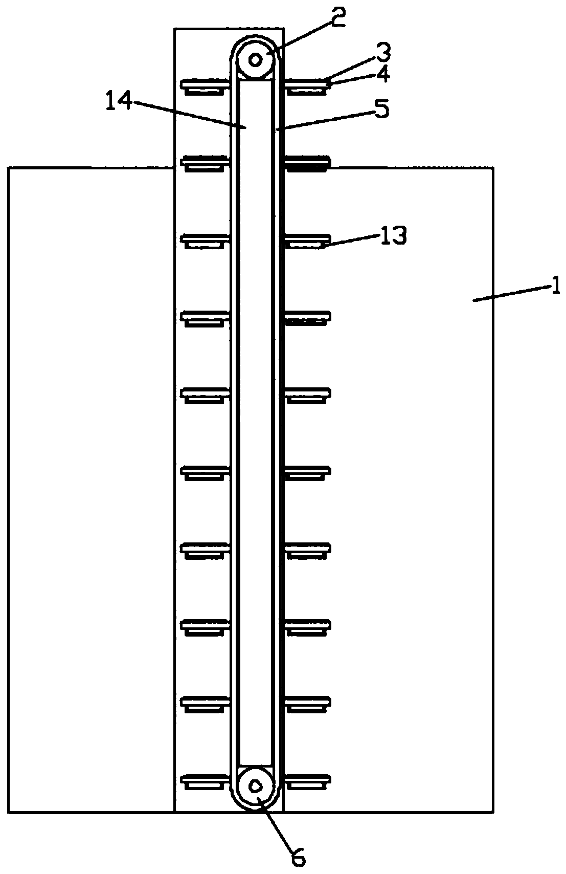
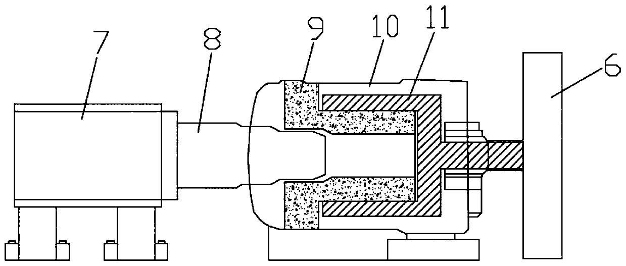
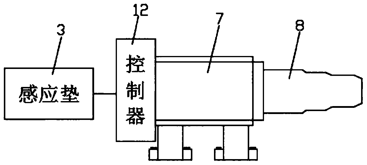
[0036] Please refer to the attached Figure 1-4 , a life-saving device for a high-rise building of the present invention, the life-saving device is installed on the non-window building wall 1, including an upper mounting frame, a lower mounting frame, and a pulley device, and the pulley device is arranged between the upper mounting frame and the lower mounting frame The upper mounting frame is installed on the roof of the building, the outer side of which is provided with a driven wheel 2, the lower mounting frame is arranged on the ground, and its outer side is provided with a driving wheel 6, and there is a non-deformable sleeve between the driv...


PUM


Abstract

The invention discloses a lifesaving device for a high-rise building. The lifesaving device is provided with a pulley device, and treading parts and handrails are mounted on the pulley device; escapepersonnel can slide down from one side of the pulley device through the treading parts and the handrails, in the sliding-down process, the feet tread on sensing cushions, the sensing cushions send a signal to a controller when sensing escaping of the certain personnel, and the controller receives the signal and judges the personnel number; and the pushing distance of a pushing rod is driven through the personnel number, the more the personnel are, the larger pressure applying to the pulley device is, and therefore, sufficient friction force is needed to prevent the pulley device from rotatingtoo. On the other hand, in order to avoid the situation that the friction force between the pulley device and a damping device is overlarge, and consequently a driving wheel rotates too slow, the pushing distance of the pushing rod needs to be controlled by judging the personnel number; and different diameters are set on the pushing rod, therefore, extrusion force applying to a rubber sleeve is different, the larger the push-out distance of the push rod is, the larger the extrusion force applying to the rubber sleeve is, and accordingly the friction force between the rubber sleeve and a connecting part is larger.

Description

technical field [0001] The invention relates to a lifesaving device, in particular to a lifesaving device for a high-rise building. Background technique [0002] The height of high-rise buildings generally exceeds 100m, and the height of supertall buildings can even reach 300m. This has brought great challenges to the traditional fire protection system. Although high-rise and super high-rise buildings are equipped with automatic sprinkler systems and internal fire hoses. However, the scope of action of the automatic sprinkler system is relatively limited; while the internal fire hose must be manipulated by personnel entering the fire scene. What's more deadly is that if the fire causes damage to the electrical system of a high-rise building, the automatic sprinkler system and internal fire hoses will all fail. And the employed aerial ladder car height of fire-fighting is then generally within 100m at present, for the high-rise building fire exceeding the aerial ladder car...

Claims


Application Information

Patent Timeline
Patent Type & Authority Patents(China)
IPC IPC(8): A62B1/00
CPCA62B1/00
Inventor 尹佳王堂锐张娜
Owner LUSHAN COLLEGE OF GUANGXI UNIV OF SCI & TECH
Learn More