
Automobile braking arm tool

A technology of automobile braking and tooling, which is applied in the direction of manufacturing tools, metal processing equipment, and drilling molds for workpieces, etc., and can solve the problem of large dimensional errors, the incompatibility between the pin hole 1005 and the second hole 1004, and the brake arm 1001 Scrap and other issues, to achieve the effect of high stability

Inactive Publication Date: 2018-07-13
凯瑞克(宁波)体育用品有限公司
View PDF0 Cites 0 Cited by
  • Summary
  • Abstract
  • Description
  • Claims
  • Application Information

AI Technical Summary

Problems solved by technology

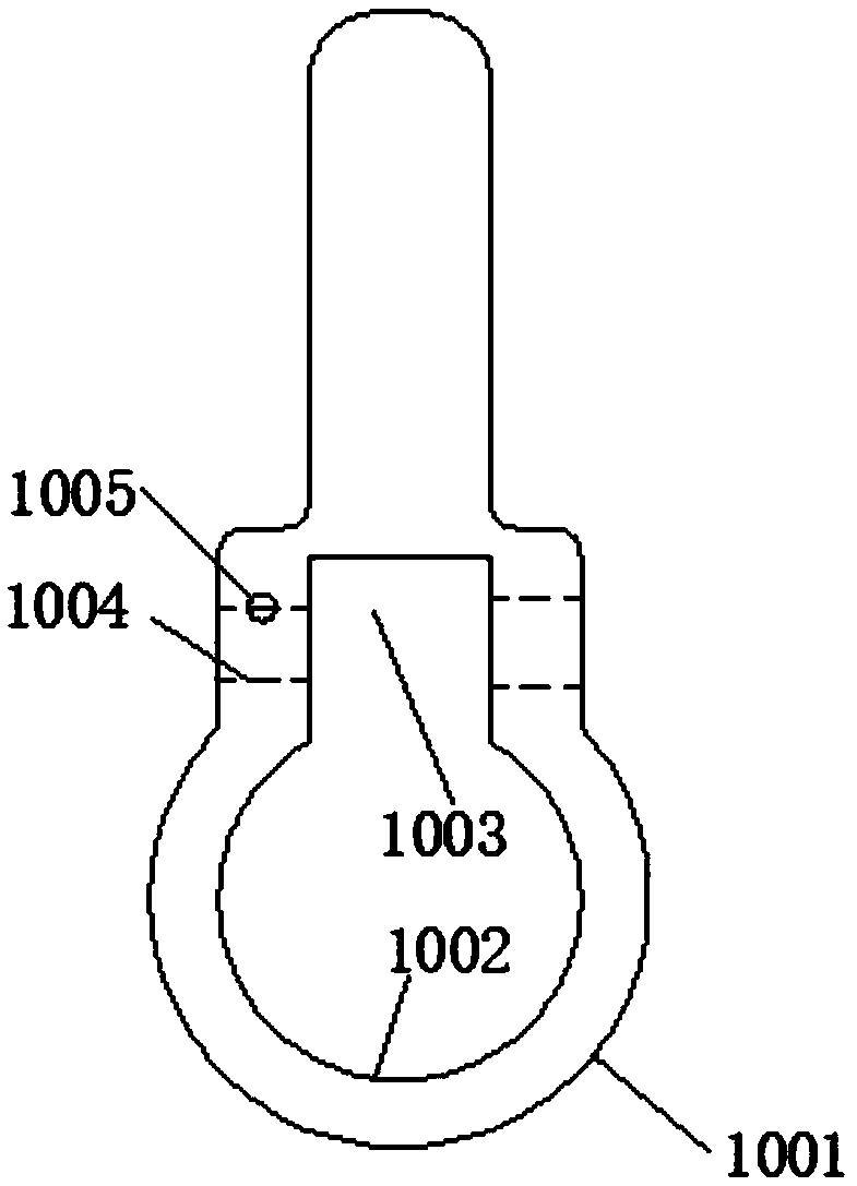
[0002] like image 3 Shown: the upper end of the hole two 1004 of the brake arm 1001 of the automobile has a pin hole 1005, and half the diameter of the pin hole 1005 is in the hole two 1004, which is intercommunicative. The pin hole 1005 of the brake arm 1001 is processed first Process the pin hole 1005, and then process the second hole 1004. However, the center distance between the second hole 1004 and the first hole 1002 has high technical requirements, and the verticality with the square groove 1003 must also meet the technical requirements, so the pin hole 1005 During processing, the X-direction and Y-direction dimensions of hole 1002 must meet the requirements of the drawing, otherwise, after the subsequent processing of hole 2 1004, the pin-through hole 1005 and hole 2 1004 will not be able to communicate with each other, or the intercommunication requirements will not meet the technical requirements , causing the brake arm 1001 to be scrapped. In conventional processing, hole 1002 is used as the reference line to fill points. However, the size error of hole 1002 in the X direction and Y direction is relatively large, and it is difficult to ensure that it is consistent with the square groove 1003. degree of position

Method used


Image

  • Automobile braking arm tool
  • Automobile braking arm tool
  • Automobile braking arm tool

Examples


Embodiment Construction

[0010] The technical solutions of the present invention will be further specifically described below through the embodiments and in conjunction with the accompanying drawings.

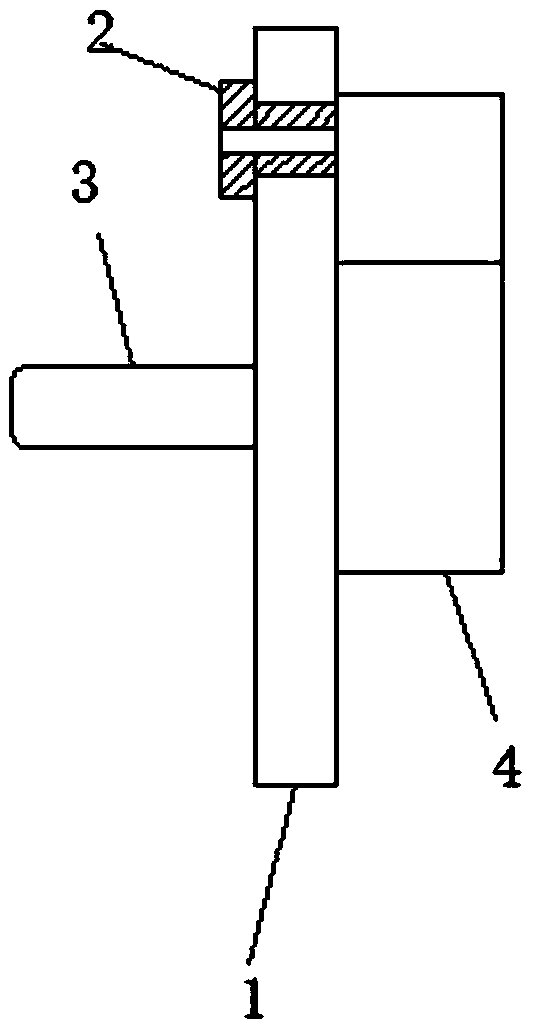
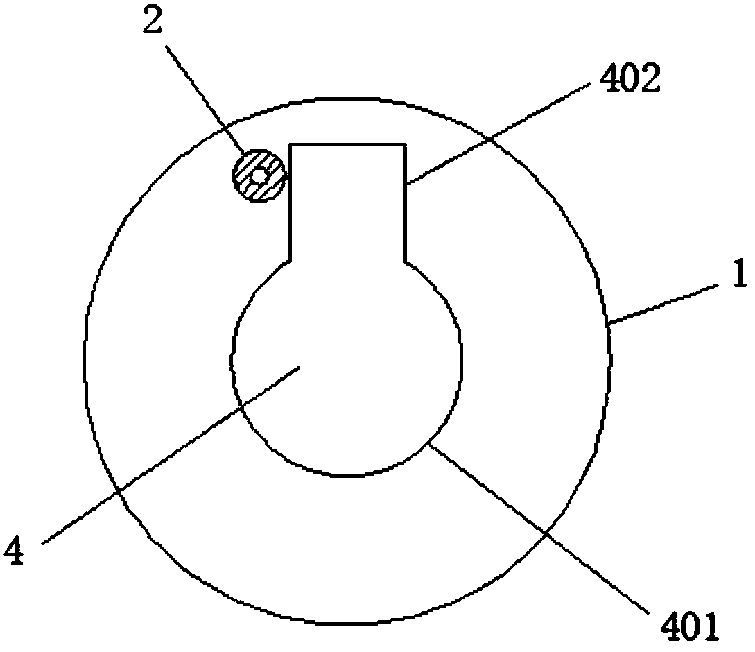
[0011] Such as Figure 1 ~ Figure 2 As shown, the automobile brake arm tooling includes a template 1, a drill sleeve 2, a handle 3, and a positioning block 4. The template 1 has a handle 3 on the left, a positioning block 4 on the right, and a positioning circle under the positioning block 4. 401, a positioning block 402 is set on the positioning circle 401, and a drill sleeve 2 is arranged on the left side of the positioning block 402. The positioning block of the present invention is positioned with the hole 1 and the square groove of the brake arm, and the drill sleeve is used as a reference to process the pin Hole, so that the position of the pin hole and the hole 1 and the square groove meet the technical requirements, and the stability is high.

[0012] Those skilled in the art also understand t...


PUM


Abstract

The invention discloses an automobile braking arm tool. The automobile braking arm tool comprises a mold plate, a drill sleeve, a handle and a positioning block; the handle is arranged on the left ofthe mold plate, and the positioning block is arranged on the right of the mold plate; a positioning circle is arranged below the positioning block, and is provided with a positioning square block; andthe drill sleeve is arranged on the left side of the positioning square block. According to the automobile braking arm tool, according to the positioning block, positioning is performed through a first hole of a braking arm and a square groove and a pin penetrating hole is machined with the drill sleeve as the benchmark, the positions of the pin penetrating hole, the first hole and the square groove are made to meet the technical requirements, and stability is high.

Description

technical field [0001] The invention relates to the technical field of automobile parts and equipment, in particular to automobile brake arm tooling. Background technique [0002] Such as image 3 Shown: the upper end of the hole two 1004 of the brake arm 1001 of the automobile has a pin hole 1005, and half the diameter of the pin hole 1005 is in the hole two 1004, which is intercommunicative. The pin hole 1005 of the brake arm 1001 is processed first Process the pin hole 1005, and then process the second hole 1004. However, the center distance between the second hole 1004 and the first hole 1002 has high technical requirements, and the verticality with the square groove 1003 must also meet the technical requirements, so the pin hole 1005 During processing, the X-direction and Y-direction dimensions of hole 1002 must meet the requirements of the drawing, otherwise, after the subsequent processing of hole 2 1004, the pin-through hole 1005 and hole 2 1004 will not be able to c...

Claims


Application Information

Patent Timeline
Patent Type & Authority Applications(China)
IPC IPC(8): B23B47/28B23B49/02
CPCB23B47/28B23B49/02
Inventor 王海军
Owner 凯瑞克(宁波)体育用品有限公司
Learn More