Device for researching mechanical property of anchor rod under action of impact force as well as use method of device

A technology of bolt mechanics and impact force, applied in the field of geotechnical mechanics, can solve problems such as deep rock mass disasters and failure of bolt support in high-stress engineering surrounding rock, achieving simple operation, saving test costs, and intuitive and real tests. Effect

Active Publication Date: 2018-07-13
HUNAN UNIV OF SCI & TECH
View PDF6 Cites 3 Cited by
  • Summary
  • Abstract
  • Description
  • Claims
  • Application Information

AI Technical Summary

Problems solved by technology

Under certain conditions, even small disturbances may induce the failure of high-stress engineering surrounding rock bolt support, thus causing deep rock mass disasters

Method used


Image

  • Device for researching mechanical property of anchor rod under action of impact force as well as use method of device
  • Device for researching mechanical property of anchor rod under action of impact force as well as use method of device
  • Device for researching mechanical property of anchor rod under action of impact force as well as use method of device

Examples


Embodiment 1

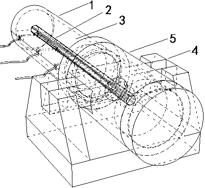
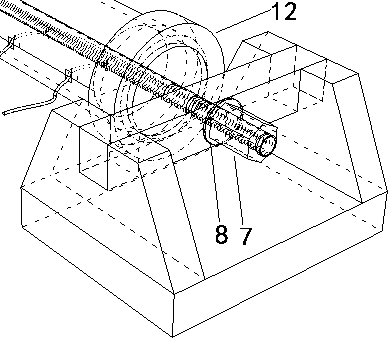
[0037] as attached Figure 1-4 As shown, the research device for the mechanical properties of the anchor rod under the action of impact force includes a casing, an anchor rod, an anchoring agent, a fixed end and an impacted end. The anchoring agent anchors the anchor rod in the casing, and one end of the anchor rod is outside the casing. The end is fixedly connected to the ground through the fixed end, and the impacted end passes through the fixed end and contacts the casing.

[0038] The fixed end includes a fixed block, a nut, a gasket and a fixed seat. The fixed block is long and has a hole in the middle, and the anchor rod passes through the hole. The nut matches the thread of the anchor rod, and the nut and the gasket are installed on the anchor On the rod, the position of the fixed block is limited, the two ends of the fixed block are located outside the impacted end, the two ends of the fixed block are fixedly connected with the fixed seat, and the fixed seat is fixedly...

Embodiment 2

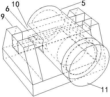
[0054] The difference between this embodiment and embodiment 1 is: 1. the structure of the impact protection sleeve is different, as attached Figure 6 As shown, one end of the impact protection sleeve in this embodiment is a smaller cylinder, which is inserted into the casing, and the other end is a larger cylinder, which accepts the insertion of the impacted end; 2. The structure of the impacted block is different , in this implementation, the end with a larger outer diameter of the impacted block is a cylinder, which accepts the insertion of the incident rod. In this embodiment, the impact protection and the impacted block are coaxially and stably connected with the bushing, the impact end, and the incident rod, which is beneficial to the transmission of impact force.


PUM


Abstract

The invention aims to provide a device and a method for researching the dynamic mechanical property of a pre-stressed anchor rod, which are simple and convenient in operation and high in practicability. The device for researching the mechanical property of an anchor rod under the action of an impact force comprises a casing pipe, the anchor rod, an anchoring agent, a fixed end and an impacted end,wherein the anchoring agent anchors the anchor rod in the casing pipe; one end of the anchor rod is positioned outside the casing pipe, and the end is fixedly connected with the ground through the fixed end; the impacted end penetrates through the fixed end and is in contact with the casing pipe. The device has the following beneficial effects: 1, the limitation that the conventional research onthe mechanical property of the anchor rod only takes static load into consideration is overcome; 2, the mechanical characteristic of the pre-stressed anchor rod under impact can be simulated and researched truly; 3, the instantaneous impact condition can be observed and recorded conveniently, and the device is simple and convenient to operate, economic and practical; 4, the test is more intuitiveand real; 5, firstly, the existence of the impacted end performs a buffer and protection effect on the casing pipe; secondly, the impacted end can be detached, so that mounting of the fixed end is facilitated; finally, the impacted end can be detached and changed, so the test cost is reduced.

Description

technical field [0001] The invention relates to the field of rock and soil mechanics, in particular to a device and method for studying the dynamic mechanical properties of bolts. Background technique [0002] Prestressed anchoring technology is to use anchor rods or anchor cables to reinforce the rock mass. It can significantly improve the surrounding rock structure and improve its stability. It is a simple, safe, reliable and cost-effective reinforcement technology that has been widely used in mining. Engineering, water conservancy and hydropower, railway transportation and urban construction and other fields, and have achieved good economic and social benefits. However, with the increase of the mining depth of rock mass engineering, the mining conditions tend to be more complicated, and the problems of bolt support failure are prominent, such as the disappearance of prestress, the falling off of the supporting plate and the breaking of the bolt, etc., which have become a ...

Claims


Application Information

Patent Timeline
Patent Type & Authority Applications(China)
IPC IPC(8): G01N3/307G01N3/02G01N3/06G01M7/08
CPCG01M7/08G01N3/02G01N3/06G01N3/062G01N3/307G01N2203/001G01N2203/0044G01N2203/0676Y02E30/30
Inventor 吴秋红李羲
Owner HUNAN UNIV OF SCI & TECH
Why Eureka
Try Eureka