
Method and device for multiplexing and demultiplexing of vortex beams

A vortex beam and demultiplexing technology, which is applied in the field of vortex beam multiplexing and demultiplexing, can solve the problems of beam mismatch and inconvenient multiplexing

Active Publication Date: 2020-02-18
SUN YAT SEN UNIV
View PDF8 Cites 0 Cited by
  • Summary
  • Abstract
  • Description
  • Claims
  • Application Information

AI Technical Summary

Problems solved by technology

Ruffato et al. of the University of Padua used the above method of transformation optics to convert the output beams of multiple standard single-mode fibers into a composite vortex beam, which presents a light intensity distribution similar to a long ellipse, rather than a circularly symmetrical Gaussian beam. So it doesn't match the beam coming out of the fiber
However, if this solution transforms the Gaussian light emitted by the fiber into a light spot similar to a long ellipse, it is not convenient for multiplexing

Method used


Image

  • Method and device for multiplexing and demultiplexing of vortex beams

Examples


Embodiment Construction

[0024] The accompanying drawings are for illustrative purposes only, and should not be construed as limitations on this patent; in order to better illustrate this embodiment, certain components in the accompanying drawings will be omitted, enlarged or reduced, and do not represent the size of the actual product; for those skilled in the art It is understandable that some well-known structures and descriptions thereof may be omitted in the drawings. The positional relationship described in the drawings is for illustrative purposes only, and should not be construed as a limitation on this patent.

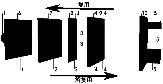
[0025] Such as figure 1 As shown, from left to right, it represents the process that the composite vortex beam is divided into several parallel vortex beams after passing through the system. And this process can be used in reverse. Conversely, from right to left is the process of transforming several non-coaxial parallel vortex beams into coaxial composite vortex beams through the sy...


PUM


Abstract

The invention relates to the technical field of vortex light field regulation in the field of optics, in particular to a vortex beam multiplexing and demultiplexing method and device through which thetechnical problem of vortex beam multiplexing and demultiplexing in existing communication systems can be solved. By the method, on one hand, noncoaxial vortex beams can be combined to be a coaxial combined vortex beam to realize multiplexing of the vortex beams; on the other hand, the coaxial combined vortex beam can be separated to be the noncoaxial vortex beams to realize demultiplexing of thecoaxial vortex beam. The device needs to perform two times of optical geometric conversion, an optical element is inserted at a beam focusing position for beam deflection between the two times of conversion so as to change arrival position of vortex light different in topological charge. The device can add a spiral phase onto an output end face for vortex beam demultiplexing to enable vortex beams to be output as separated planar wave beams, so that the beams can be easily focused and coupled into optical fiber for the convenience of being compatible with existing communication system.

Description

technical field [0001] The present invention relates to the technical field of regulation and control of vortex light field in the field of optics, more specifically, to a method and device for multiplexing and demultiplexing of vortex beams. Background technique [0002] From the 1930s, people began to realize that beams can carry more complex angular momentum. Until 1992, Allen et al. first discovered a beam with a helical phase wavefront factor exp(ilθ), which can carry lħ per photon Orbital angular momentum (OAM), where l is the topological charge, and θ is the azimuth in the cylindrical coordinate system. Because the beam carrying orbital angular momentum has a spiral phase structure, we usually call it a vortex beam. Since Allen et al. have successively reported related papers on vortex beams, vortex beams have rapidly become a research hotspot around the world and have been applied in practice. In recent years, the application of vortex beams has been involved in ma...

Claims


Application Information

Patent Timeline
Patent Type & Authority Patents(China)
IPC IPC(8): G02B27/10
CPCG02B27/106
Inventor 李朝晖刘志兵杨继顺肖文达高社成熊松松
Owner SUN YAT SEN UNIV
Learn More