
Railway traffic communication train identifying antenna

A technology for railway traffic and antenna identification, which is applied to antennas, antenna supports/installation devices, electrical components, etc., can solve the problems of easy damage, cumbersome installation process, easy accumulation of water and damp at the installation location, etc., to avoid the accumulation of rainwater, Avoid sun exposure

Active Publication Date: 2018-07-13
安徽伟迈信息技术有限公司
View PDF10 Cites 2 Cited by
  • Summary
  • Abstract
  • Description
  • Claims
  • Application Information

AI Technical Summary

Problems solved by technology

[0002] As a rail transit communication device, railway antennas play an important role in train identification. Most of the current railway antennas are installed under the rails and sleepers. Although this position is easier to detect train information, there are still many disadvantages. For installation, the railway antenna needs to be installed under the rails and sleepers, so as not to affect the normal running of the train. Therefore, the ballast under the rails needs to be cleaned before the railway antenna can be installed. The installation process is cumbersome, and when the train passes It is inevitable that vibration will be generated, and the installation position is lower and prone to water accumulation, so the railway antenna is always in this environment and it is easy to be damaged.

Method used


Image

  • Railway traffic communication train identifying antenna
  • Railway traffic communication train identifying antenna
  • Railway traffic communication train identifying antenna

Examples


Embodiment Construction

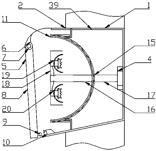
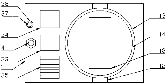
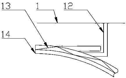
[0023] The present invention is specifically described below in conjunction with accompanying drawing, as Figure 1-7 As shown, a train identification antenna for railway traffic communication includes an installation shell 1, and the installation shell 1 is fixedly installed in a rectangular slot 2, and the rectangular slot 2 is opened in the middle of the vertical plane of the platform on one side of the rail Position, the bottom surface of the rectangular groove 2 is provided with a fixing hole 3, and a fixing bolt 4 is arranged in the fixing hole 3, and a protection device 5 is provided on the left side of the installation shell 1, and the protection device 5 is located on the left side of the installation shell 1. The bushing 6 fixedly connected to the inner surface of the installation shell 1, the pin shaft 7 located in the bushing 6 and rotatably connected to the bushing 6, the protective cover 8 located below the pin shaft 7 and fixedly connected to the pin shaft 7, the...


PUM


Abstract

The invention discloses a railway traffic communication train identifying antenna. The railway traffic communication train identifying antenna comprises a mounting case, inside which a signal aggregating device is arranged; the signal aggregating device is composed of an aggregating device support, an aggregating curved support and an aggregating plate, wherein the aggregating device support is mounted inside the mounting case and fixedly connected to the top surface and the bottom surface inside the mounting case, the aggregating curved support is arranged on the right of a protecting cover,mounted inside the mounting case and fixedly connected with the aggregating device support, and the aggregating plate is arranged on the left of the aggregating curved support and fixedly connected tothe left surface of the aggregating curved support; the left of the aggregating plate is provided with an antenna fixing device, which is composed of a mounting column, an antenna case, a signal receiver and a signal transmitter, wherein the mounting column is fixedly connected on the right of the aggregating curved support and in the middle of the bottom surface of the mounting case and arrangedinside a mounting hole in a sleeve mode, the antenna case is arranged on the left of the mounting column and fixedly connected to the left surface of the mounting column, the signal receiver is arranged inside the antenna case, and the signal transmitter is arranged under the signal receiver. The railway traffic communication train identifying antenna has the advantages of being simple in structure and high in practicality.

Description

technical field [0001] The invention relates to the technical field of railway antennas, in particular to a train identification antenna for railway traffic communication. Background technique [0002] As a rail transit communication device, railway antennas play an important role in train identification. Most of the current railway antennas are installed under the rails and sleepers. Although this position is easier to detect train information, there are still many disadvantages. For installation, the railway antenna needs to be installed under the rails and sleepers, so as not to affect the normal running of the train. Therefore, the ballast under the rails needs to be cleaned before the railway antenna can be installed. The installation process is cumbersome, and when the train passes Vibration is unavoidable, and the installation position is lower and prone to water accumulation, so the railway antenna is easily damaged in this environment. Contents of the invention ...

Claims


Application Information

Patent Timeline
IPC IPC(8): H01Q1/12H01Q1/22H01Q19/12
CPCH01Q1/12H01Q1/22H01Q19/12
Inventor 宫长河
Owner 安徽伟迈信息技术有限公司
Learn More