
An automatic riveting machine for the assembly of the fan shaft sleeve and the middle plate

A fan shaft and riveting machine technology, applied in the field of automatic riveting machines, can solve the problems of low riveting efficiency, reduced work efficiency, increased riveting cost, etc., and achieves the effect of ensuring riveting quality, maintaining riveting efficiency, and preventing assembly errors.

Active Publication Date: 2019-06-04
ZHE JIANG YILIDA VENTILATOR CO LTD
View PDF9 Cites 0 Cited by
  • Summary
  • Abstract
  • Description
  • Claims
  • Application Information

AI Technical Summary

Problems solved by technology

[0002] The riveting process of the fan shaft sleeve and the center plate needs to go through three steps of assembly, pressure riveting and upsetting teeth. The traditional riveting process requires multiple equipment. It is necessary to use upsetting equipment, and when the product that has been processed in one process is transferred to another equipment, it will consume a lot of time, resulting in low riveting efficiency, and purchasing multiple equipment for riveting will lead to riveting The cost increases, which leads to an increase in the overall cost of the fan, and it is easy to make mistakes when installing the fan shaft sleeve and the center plate manually, resulting in poor assembly quality, especially a screw hole on the shaft sleeve needs to face the balance on the center plate Holes, once the directions of the two are staggered, it will affect its performance, and the way of manual alignment will reduce the work efficiency again

Method used


Image

  • An automatic riveting machine for the assembly of the fan shaft sleeve and the middle plate
  • An automatic riveting machine for the assembly of the fan shaft sleeve and the middle plate
  • An automatic riveting machine for the assembly of the fan shaft sleeve and the middle plate

Examples


Embodiment Construction

[0019] Below in conjunction with accompanying drawing and specific embodiment the present invention will be described in further detail:

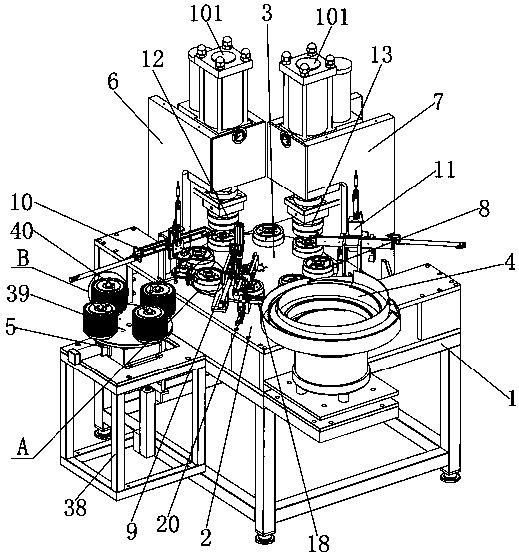
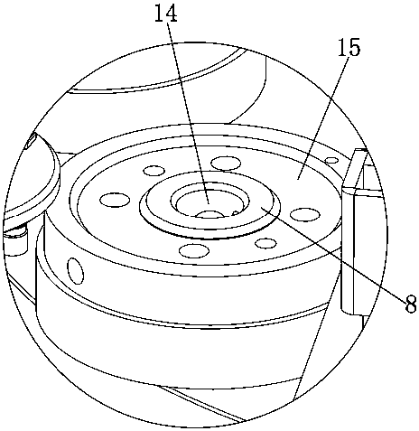
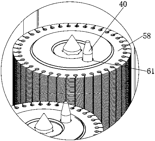
[0020] see Figure 1 to Figure 6 , the present invention provides an automatic riveting machine for the assembly of the fan shaft sleeve and the middle plate, including a frame 1, a workbench 2 is arranged above the frame 1; an indexing plate 3 is arranged on the workbench 2; The periphery of the workbench 2 is provided with a vibrating plate 4, a pneumatic indexing mechanism 5, a riveting mechanism 6, and an upsetting gear mechanism 7; the center of the workbench 2 is provided with an indexing plate 3; The charging table 8 is evenly distributed on the circumference; the outer ring of the indexing plate 3 is provided with a shaft sleeve grasping mechanism 9, a middle plate grasping mechanism 10 corresponding to the position of the pneumatic indexing mechanism 5, and a blanking mechanism 11; The pressure riveting mechanism 6 is provided wit...


PUM


Abstract

An automatic riveting machine for draught fan shaft sleeve and middle disc assembling comprises a rack. A workbench is arranged above the rack. An index plate is arranged on the workbench. A vibrationdisc, a pneumatic indexing mechanism, a pressing-rivet mechanism and a tooth upsetting mechanism are arranged on the periphery of the workbench. The index plate is arranged at the center of the workbench and provided with a plurality of loading tables evenly distributed along the circumference. The outer ring of the index plate is provided with a shaft sleeve grabbing mechanism, a middle disc grabbing mechanism corresponding to the pneumatic indexing mechanism in position, and a discharging mechanism. The pressing-rivet mechanism is provided with pressing-rivet dies corresponding to the loading tables in position. The tooth upsetting mechanism is provided with tooth upsetting dies corresponding to the loading tables in position. According to the automatic riveting machine for draught fanshaft sleeve and middle disc assembling, all procedures in the riveting process can be finished on one device, errors caused by manual assembling can be avoided, the riveting quality is guaranteed, and the efficient riveting efficiency can be constantly kept.

Description

technical field [0001] The invention relates to an automatic riveting machine, in particular to an automatic riveting machine used for assembling a fan shaft sleeve and a center plate. Background technique [0002] The riveting process of the fan shaft sleeve and the center plate needs to go through three steps of assembly, pressure riveting and upsetting teeth. The traditional riveting process requires multiple equipment. It is necessary to use upsetting equipment, and when the product that has been processed in one process is transferred to another equipment, it will consume a lot of time, resulting in low riveting efficiency, and purchasing multiple equipment for riveting will lead to riveting The cost increases, which leads to an increase in the overall cost of the fan, and it is easy to make mistakes when installing the fan shaft sleeve and the center plate manually, resulting in poor assembly quality, especially a screw hole on the shaft sleeve needs to face the balanc...

Claims


Application Information

Patent Timeline
Patent Type & Authority Patents(China)
IPC IPC(8): B21D39/00
CPCB21D39/00
Inventor 章启忠战长珉应云建熊年保
Owner ZHE JIANG YILIDA VENTILATOR CO LTD
Learn More