Refrigerator

A technology for refrigerators and outer boxes, which is applied in household refrigerators, ice making, ice making, etc., and can solve the problems of deterioration of energy-saving performance of refrigerators on the top surface of the mechanical room, reduction of heat insulation performance, and the use of vacuum insulation materials for heat insulation materials, etc. , to achieve better drainage, maintain heat insulation, and reduce the probability of occlusion

Active Publication Date: 2018-07-17
MITSUBISHI ELECTRIC CORP
View PDF11 Cites 1 Cited by
  • Summary
  • Abstract
  • Description
  • Claims
  • Application Information

AI Technical Summary

Problems solved by technology

In addition, if there is a drainage path between the drip tray at the lower part of the cooler and the machine room at the lower back of the refrigerator, it is impossible to arrange a vacuum heat insulating material inside the heat insulating material, and the cooler room and Boundary between mechanical rooms, thermal insulation performance is reduced
As a result, the energy saving performance of the refrigerator deteriorates, or dew condensation occurs on the ceiling of the machine room.

Method used


Image

  • Refrigerator
  • Refrigerator
  • Refrigerator

Examples


Embodiment approach 1

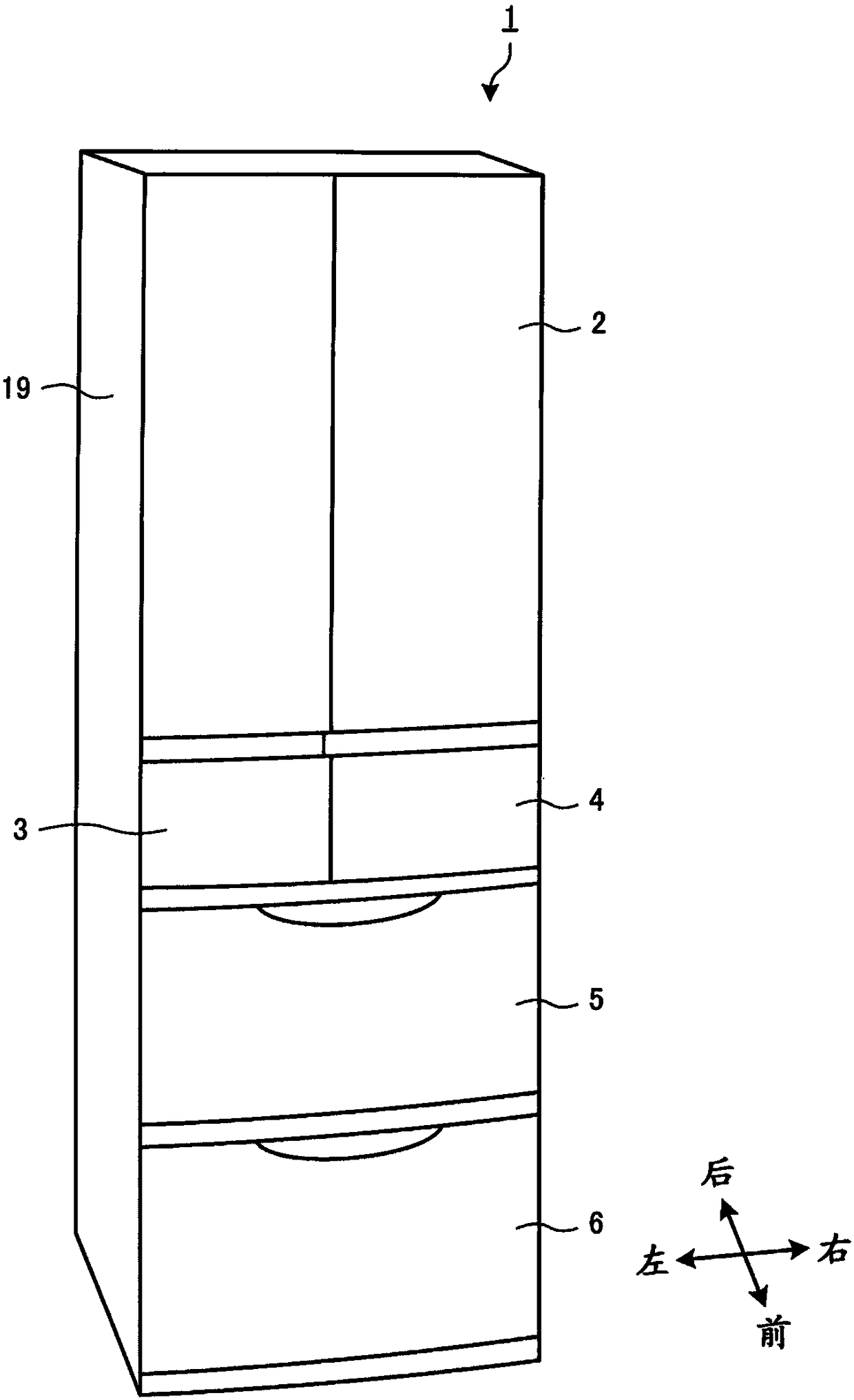
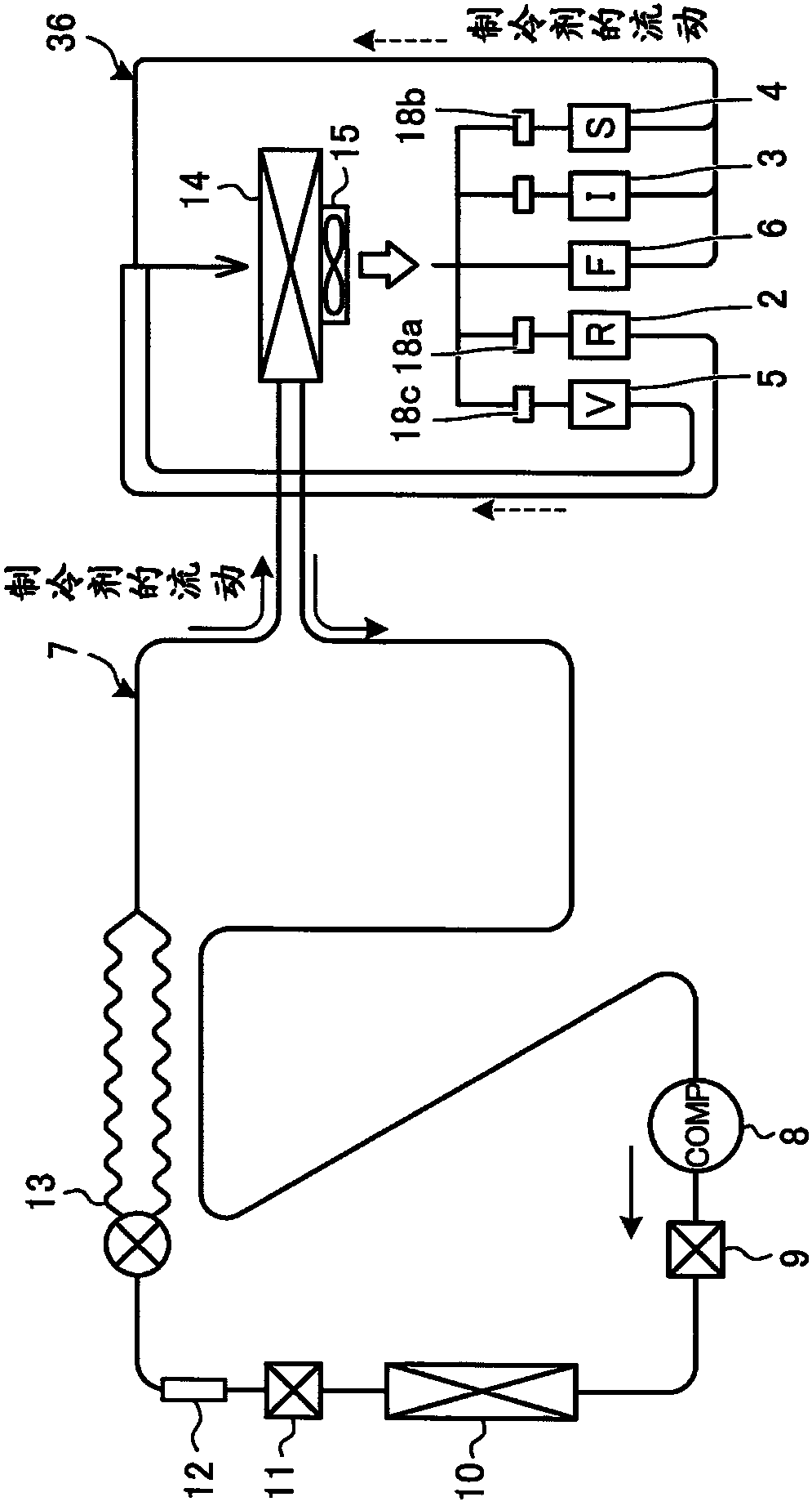
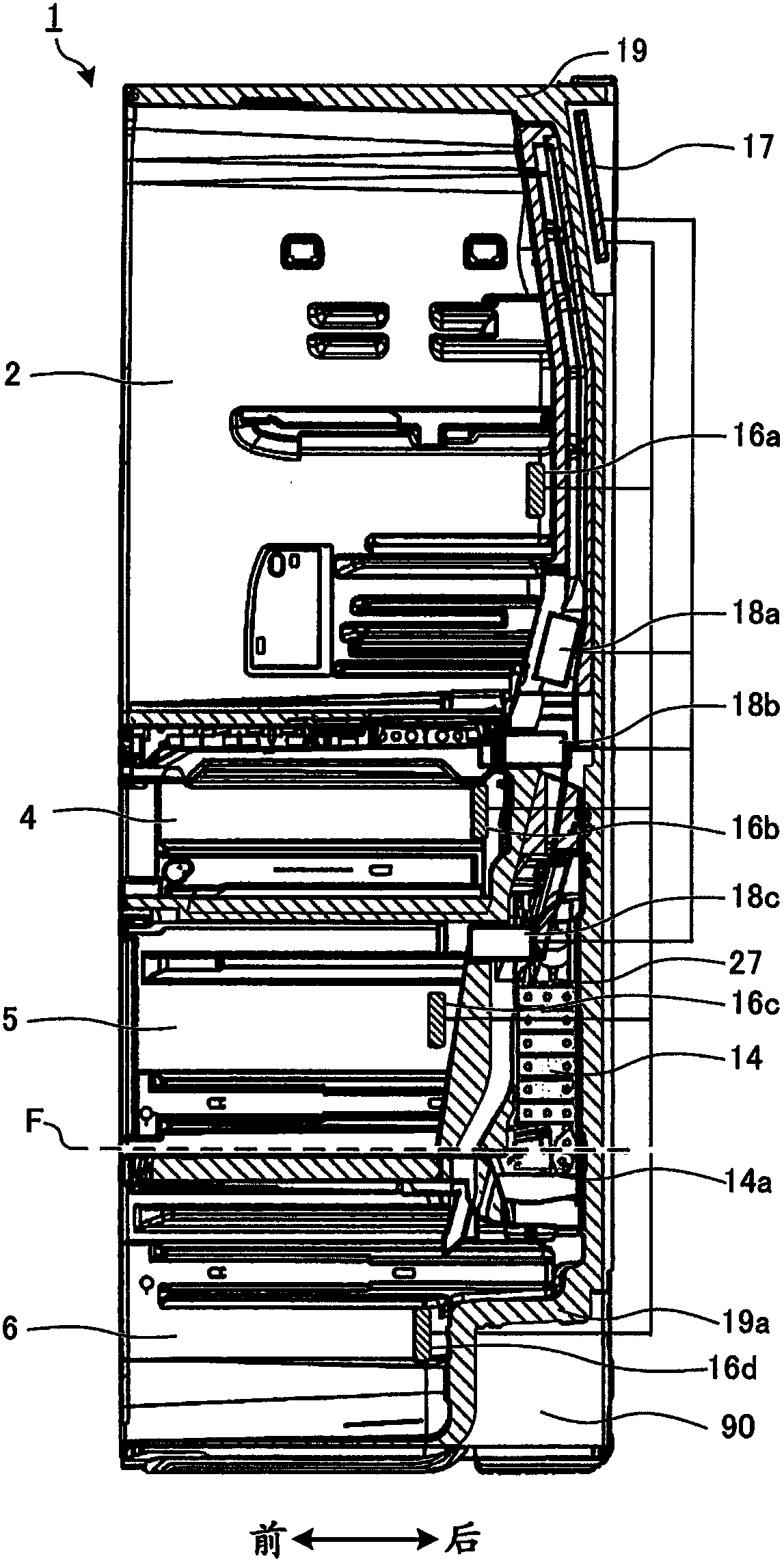
[0061] based on Figure 1 ~ Figure 4 The configuration of the refrigerator 1 will be described. figure 1 It is a perspective view showing the appearance of the refrigerator according to Embodiment 1 of the present invention. figure 2 It is a schematic diagram showing the refrigerant circuit and the air circulation path of the refrigerator according to Embodiment 1 of the present invention. image 3 It is a side cross-sectional view showing the refrigerator according to Embodiment 1 of the present invention. Figure 4 It is a schematic configuration diagram of the machine room on the back of the refrigerator according to Embodiment 1 of the present invention.

[0062] Such as figure 1 as well as image 3 As shown, the refrigerator 1 is equipped with the heat insulation box 19 comprised in the shape of a vertically long cuboid, and the heat insulation box 19 has several storage rooms formed. Refrigerator 1 has storage compartments arranged in the order of refrigerating com...

Embodiment approach 2

[0130] In Embodiment 1, the drain path is provided at the rear end along the rear surface of the refrigerator from the inlet to the outlet. In Embodiment 2, the configuration in which the drain path is inclined on the outlet side will be described. Hereinafter, only the points of difference from Embodiment 1 will be described, and other configurations will have the same configuration.

[0131] Figure 34 It is a figure which shows the partial side cross-sectional view which shows the structure of a part of cooler room and a machine room concerning Embodiment 2 of this invention. The inlet 183 of the drainage path 182 is, for example, circular, elliptical, or oblong, or a combination of a semi-ellipse and a rectangle, or a combination of a semi-oblong and a rectangle, and the rear side reaches almost the rearmost part of the water receiving surface. In addition, the outlet 184 is formed, for example, in a substantially circular cross-sectional shape. Such as Figure 34 As s...


PUM


Abstract

A refrigerator is provided with: a thermal insulation casing which is provided with an inner housing, an outer housing and a heat insulating material between the inner housing and the outer housing; amachine room which is formed by causing a lower back surface portion of the thermal insulation casing to be depressed inwards and in which a compressor is disposed; a cooler room which is formed above the machine room and in the thermal insulation casing and in which a cooler for generating cold air is disposed; a water receiving unit which is provided below the cooler in the cooler room and which receives water from the cooler; and a discharge channel having an inlet provided to the water receiving unit and an outlet protruded to the machine room, the discharge channel penetrating a thermalinsulation wall intervened between the cooler room and the machine room so as to cause the cooler room and the machine room to communicate. On the inlet side, a cross-sectional area of the discharge channel is gradually reduced toward a downstream side, and a center position of the cross section approaches a back surface side. The discharge channel is configured integrally from the inlet to the outlet. As a result, it is possible to provide a refrigerator with good water discharge performance while maintaining thermal insulation.

Description

technical field [0001] The present invention relates to a refrigerator provided with a drainage path. Background technique [0002] In some conventional refrigerators, a water receiving part (drip pan) is provided below the cooler, and a drainage path penetrating the heat insulating wall is provided under the drip pan (for example, refer to Patent Document 1 and Patent Document 2). Patent Document 1 discloses a drainage channel provided below the vertical line with respect to the cooler, and Patent Document 2 discloses that the outlet of the drain channel protrudes from the ceiling of the machine room provided below the cooler room. Structure. When it is desired to secure a drainage path with the shortest distance, the configuration described in the above-mentioned patent document is applied. [0003] However, refrigerators are required to save space, have a large capacity, and require energy saving properties. Therefore, for example, there is also a refrigerator using a ...

Claims


Application Information

Patent Timeline
Patent Type & Authority Applications(China)
IPC IPC(8): F25D11/02F25C1/24F25D19/00F25D21/04F25D29/00
CPCF25C1/24F25D11/02F25D19/003F25D21/04F25D29/003F25D29/005F25D19/00F25D21/14F25D29/00
Inventor 中津哲史
Owner MITSUBISHI ELECTRIC CORP
Why Eureka
Try Eureka