Optical laminate and image display device

A technology of optical laminates and protective layers, applied in optics, identification devices, lighting devices, etc., can solve the problems of external light reflection and reflection, and achieve the effect of excellent anti-reflection function

Active Publication Date: 2018-07-17
NITTO DENKO CORP
View PDF26 Cites 2 Cited by
  • Summary
  • Abstract
  • Description
  • Claims
  • Application Information

AI Technical Summary

Problems solved by technology

However, in reality, due to the influence of the conductive layer forming process and the treatment to improve the toughness of the base material, even in an isotropic base material, some anisotropy will appear.
As a result, even if a circular polarizing film is installed, problems such as reflection of external light and reflection of the background may occur, which have not yet been resolved.

Method used


Image

  • Optical laminate and image display device
  • Optical laminate and image display device
  • Optical laminate and image display device

Examples


Embodiment 1

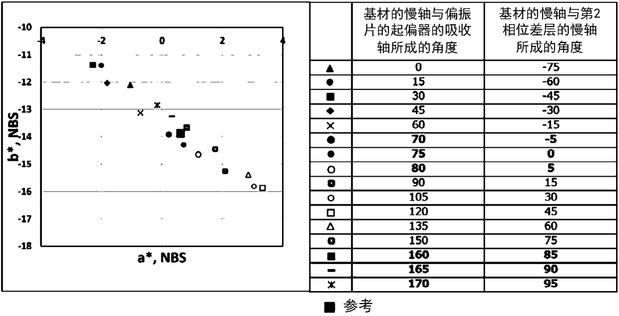
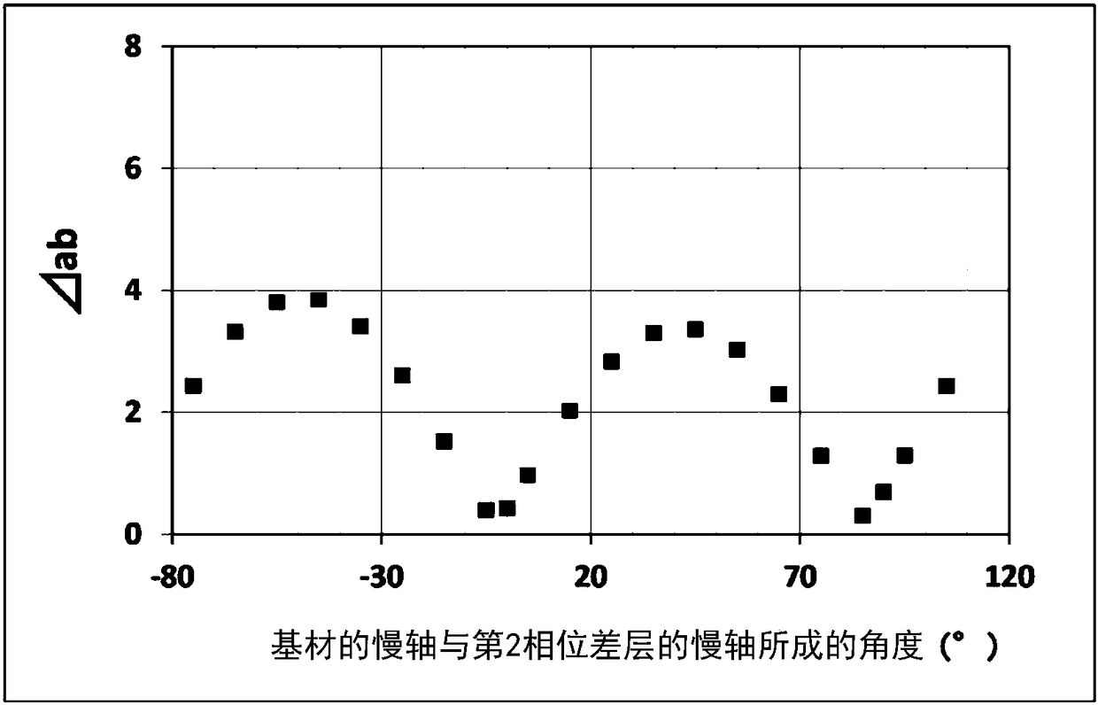
[0133] The angle formed by the slow axis of the substrate and the absorption axis of the polarizer of the polarizing plate was set to 75°. That is, the angle formed by the slow axis of the substrate and the slow axis of the second retardation layer was set to 0°.

Embodiment 2

[0135] The angle formed by the slow axis of the substrate and the absorption axis of the polarizer of the polarizing plate was set to 165°. That is, the angle formed by the slow axis of the substrate and the slow axis of the second retardation layer was set to 90°.

Embodiment 3

[0137] The angle formed by the slow axis of the substrate and the absorption axis of the polarizer of the polarizing plate was set to 70°. That is, the angle formed by the slow axis of the substrate and the slow axis of the second retardation layer was set to -5°.


PUM


Abstract

Provided is an optical laminate that has an excellent anti-reflective function despite being provided with a substrate having optical anisotropy (also referred to below as an anisotropic substrate). The optical laminate comprises the following in this order: a polarizing plate including a polarizer and a protective layer arranged on at least one side of the polarizer; a first retardation layer; asecond retardation layer; a conductive layer; and a substrate. The in-plane retardation Re(550) of the substrate is larger than 0 nm and the angle formed by the slow axis of the substrate and the slowaxis of the second retardation layer is either -5 degrees to 5 degrees or 85 degrees to 95 degrees.

Description

technical field [0001] The present invention relates to an optical laminate and an image display device using the same. Background technique [0002] In recent years, with the popularization of thin displays, displays (organic EL display devices) equipped with organic EL (Electroluminescence, electroluminescence) panels have been proposed. Since the organic EL panel has a highly reflective metal layer, problems such as reflection of external light and reflection of the background are prone to occur. Therefore, it is known to prevent these problems by disposing the circular polarizing plate on the viewing side. On the other hand, a so-called in-cell touch panel type input display device in which a touch sensor is interposed between a display unit (such as an organic EL unit) and a polarizing plate is in high demand. The input display device having such a configuration can provide a user with a natural sense of input operation because the distance between the image display u...

Claims


Application Information

Patent Timeline
IPC IPC(8): G02B5/30G02F1/1335G02F1/13363G09F9/00G09F9/30H01L27/32H01L51/50H05B33/02
CPCG02F1/1335G02F1/13363G02B5/30G09F9/00G09F9/30H05B33/02H10K59/8791
Inventor 角村浩武田健太郎饭田敏行
Owner NITTO DENKO CORP
Why Eureka
Try Eureka