
Car built-in armrest cover device

A technology for handrail covers and automobiles, which is applied in the directions of handrails, packaging, transportation and packaging, and can solve problems such as inability to manufacture handrails, automation limitations, and dependence on manual work.

Active Publication Date: 2020-10-23
HYUNDAI ENGINEERING
View PDF7 Cites 0 Cited by
  • Summary
  • Abstract
  • Description
  • Claims
  • Application Information

AI Technical Summary

Problems solved by technology

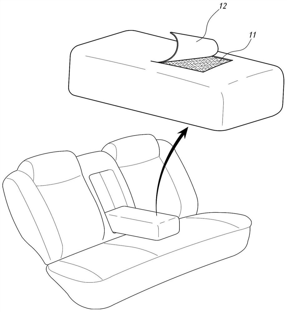
[0004] As such prior art about the manufacturing apparatus of armrests for automobiles, Korean Patent No. 1465117 can be exemplified, and Korean Patent No. 1465117 relates to a device for bonding a covering to a synthetic resin injection such as a door interior material, such as figure 1 As shown, it is impossible to manufacture the handrail in the form of inserting the stretchable filling body 11 into the bag-shaped outer skin 12.
[0005] like figure 1 As shown, in the case of an automobile armrest formed by inserting the molded filling body 11 into the inside of the pre-sewn outer skin 12, like other sewn products, the manufacturing process must rely on manual work to a large extent. , especially the process of inserting the filling body 11 into the inside of the bag-shaped outer skin 12 is limited in automation

Method used


Image

  • Car built-in armrest cover device
  • Car built-in armrest cover device
  • Car built-in armrest cover device

Examples


Embodiment Construction

[0037] Next, with reference to the accompanying drawings, the specific structure and operating principle of the present invention will be described.

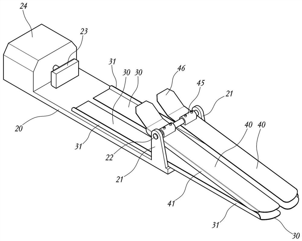
[0038] first, figure 2 It is a perspective view showing the appearance of the present invention. As shown in the figure, the present invention is a rectangular board when viewed from above. The bottom plate 30, the upper plate 40, etc. which are plate bodies protruding to the front side of the support stand 20 are comprised.

[0039] That is, if figure 2 As shown, a pair of base plates 30 are provided on the upper surface of the support platform 20, the front end of the base plate 30 protrudes toward the front of the support platform 20, and a bottom plate side wall 31 protruding upward is formed at the outer end of the base plate 30. A driving part 24 is formed at the rear end, and a two-way plate 23 is mounted on the driving part 24 .

[0040] In addition, brackets 21 protruding upward are respectively formed on the outer...


PUM


Abstract

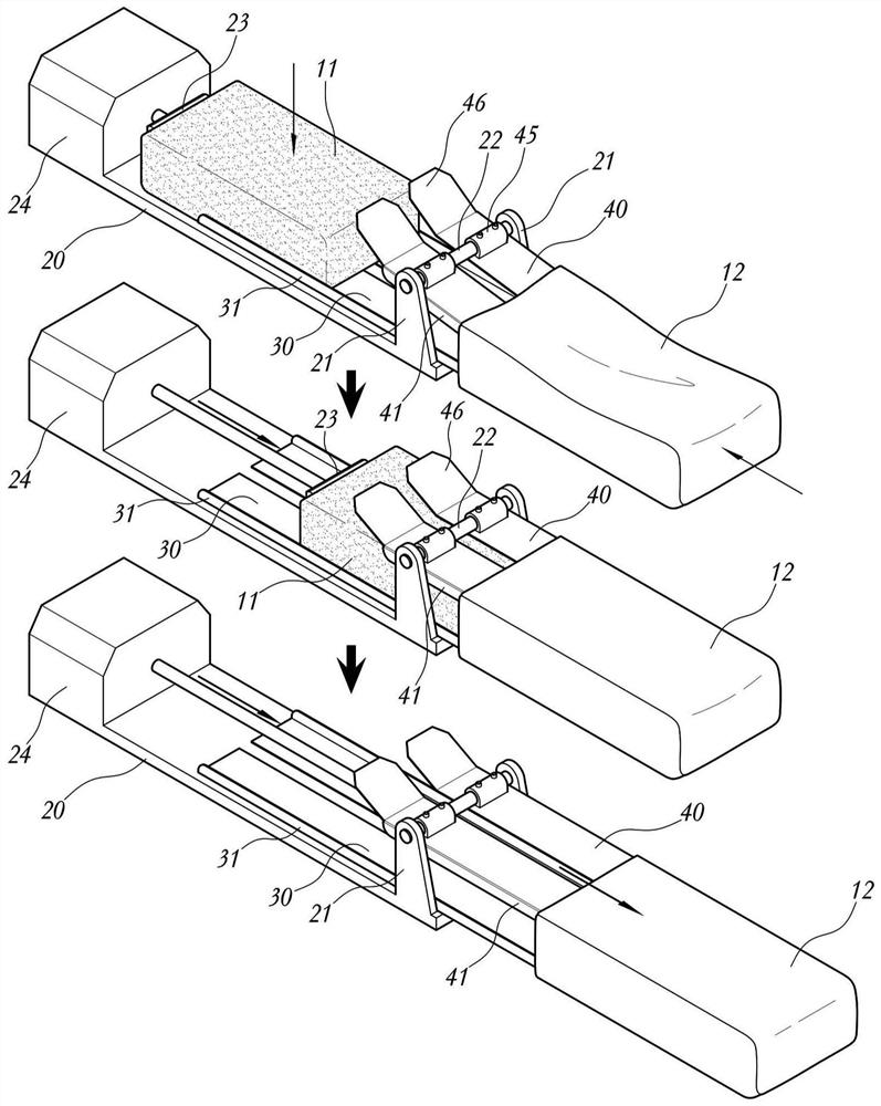
The present invention relates to an apparatus to insert a filler body prepared by molding a polyurethane foam material on an outer skin unit made of sewn leather during a process of manufacturing an armrest unit built in a vehicle. Specifically, while the outer skin unit sewn in a pocket form is coupled to the upper and lower plates, the filler body is inserted into the outer skin unit while beingpressed into the gap between the upper and lower plates. Guide blades are formed on the front ends of the upper and lower plates to automatically arrange the sewn line in the outer skin unit automatically. The apparatus is able to significantly increase productivity and manufacturing efficiency of the built-in armrest unit of a vehicle configured to include the outer skin unit and the filler bodyas well as fundamentally preventing defects occurred during manual manufacturing processes due to damage on the outer skin unit.

Description

technical field [0001] The present invention relates to a device for inserting a filling body 11 formed by polyurethane foam (polyurethane foam) or the like into an outer skin 12 sewn with leather or the like when manufacturing an automobile built-in armrest. In the state of the bottom plate 30 attached to the upper surface of the support table 20 and the upper plate 40 rotatably arranged on the upper part of the bottom plate 30, the filling body 11 is pressed between the bottom plate 30 and the upper plate 40, thereby filling the filling body 11. Inserted into the inside of the outer skin 12. Background technique [0002] In the interior of an automobile, various cushions are provided for the comfort and safety of passengers, and examples thereof include armrests. [0003] figure 1 It is a figure illustrating an armrest provided in a car seat. As shown in the figure, the armrest for automobile interior is formed by inserting a filler 11 formed of polyurethane foam (polyur...

Claims


Application Information

Patent Timeline
Patent Type & Authority Patents(China)
IPC IPC(8): B60N2/75
CPCB60N2/58B65B5/04B65B5/106B65B35/20B65B39/007B65B39/06
Inventor 姜显锡
Owner HYUNDAI ENGINEERING
Learn More