Frame-leaf structure of a door and window system

A frame sash and window sash technology, applied in the field of frame sash structure, can solve the problems of high design and production cost, many types of materials, inconvenient installation, etc.

Active Publication Date: 2020-10-23
HUNAN GOLDWELL NEW MATERIALS TECH CO LTD
View PDF6 Cites 0 Cited by
  • Summary
  • Abstract
  • Description
  • Claims
  • Application Information

AI Technical Summary

Problems solved by technology

However, in order to meet the requirements of convenient installation and aesthetics, the existing practice is to use different shapes of load-bearing beams in different parts of the doors and windows, which requires designing and manufacturing load-bearing beams of various shapes to meet the needs, especially when there are In the doors and windows that can be opened, there are many types of load-bearing beams required, which have the disadvantages of many types of materials, high design and manufacturing costs, and inconvenient installation.

Method used


Image

  • Frame-leaf structure of a door and window system
  • Frame-leaf structure of a door and window system
  • Frame-leaf structure of a door and window system

Examples


Embodiment 1

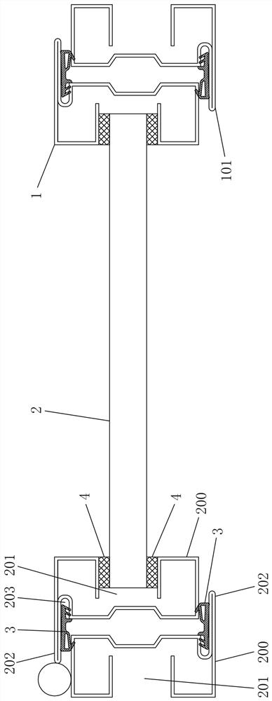
[0028] Such as figure 1 As shown, the frame structure of the door and window system of this embodiment includes a fan frame 101, and an openable window sash 1 is installed in the fan frame 101. The window sash 1 includes a frame body and a glass plate 2 installed in the frame body. The window sash 1 The frame body and the fan frame 101 are connected by load-bearing beams 200. One side of the load-bearing beam 200 is provided with a concave card slot 201, and the other side of the load-bearing beam 200 is provided with a rib 202. The rib 202 extends to the inside of the sash 101 and blocks the gap between the sash 1 and the sash 101 when the sash 1 is closed.

[0029] In this embodiment, the ribs 202 of the load-bearing beam 200 around the sash 101 are all located on the same side of the sash 101, so that the sash 1 can be rotated and opened to the other side of the sash 101 around the hinge point, and ensure that the sash 1 is closed with the sash 1. The fan frame 101 is flus...

Embodiment 2

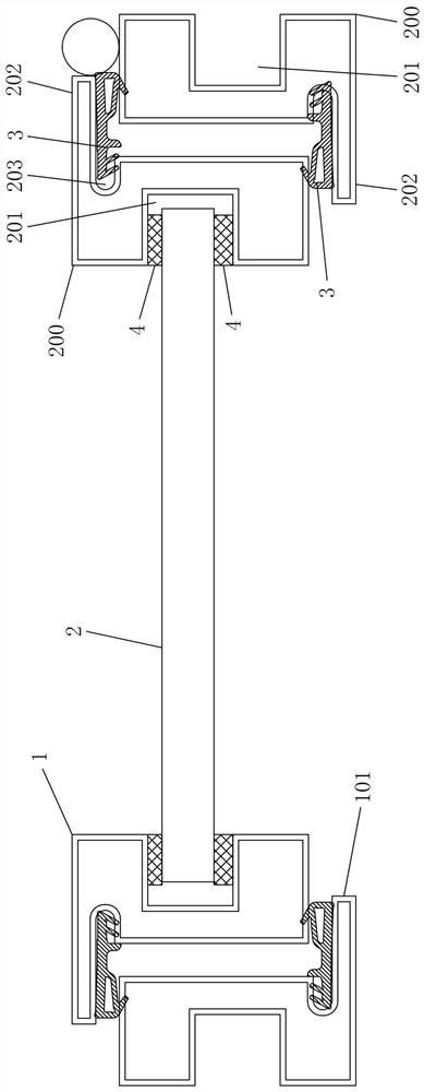
[0037] The frame and leaf structure of the door and window system of this embodiment is basically the same as that of Embodiment 1, the main difference is that, as figure 2 As shown, in this embodiment, the load-bearing beam 200 is a closed profile, which has high strength and good load-bearing performance.

Embodiment 3

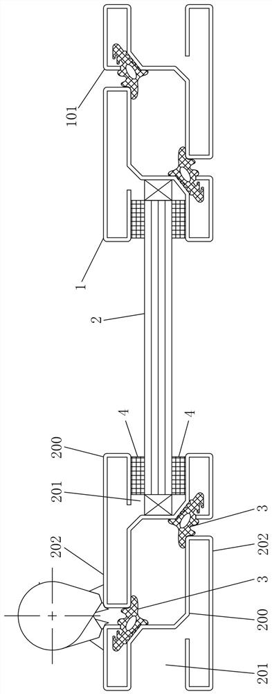
[0039] The frame and leaf structure of the door and window system of this embodiment is basically the same as that of Embodiment 1, the main difference is that, as image 3 As shown, in this embodiment, one end of the plate of the load-bearing beam 200 in the form of an open profile is located on one side of the concave groove 201 , and the other end is located on one side of the rib 202 . And in the present embodiment, the first sealing strip 3 between the rib 202 of the load-bearing beam 200 of the frame of the sash 1 and the load-bearing beam 200 around the sash 101 is installed on the load-bearing beam 200 around the sash 101, and the sash 101 The first sealing strip 3 between the rib 202 of the surrounding load-bearing beam 200 and the load-bearing beam 200 connected to form the frame of the window sash 1 is installed on the load-bearing beam 200 connected to form the frame of the window sash 1 .


PUM


Abstract

The invention discloses a sash structure of a door and window system. The sash structure of the door and window system comprises a fan frame, the fan frame is provided with an openable window sash, the window sash comprises a frame body and a glass plate which is installed in the frame body, and the frame body of the window sash and the fan frame are formed by connecting bearing beams. Inner sunken grooves are formed in one sides of the bearing beams, the other sides of the bearing beams are provided with baffle sides, and the baffle sides of the bearing beams on the periphery of the fan frameextend to the interior and cover gaps between the window sash and the fan frame when the window sash is closed. The sash structure of the door and window system has the advantages of less material preparation type and low design and production cost.

Description

technical field [0001] The invention relates to the technical field of building doors and windows, in particular to a frame leaf structure of a door and window system. Background technique [0002] The door and window system is mainly composed of a frame and a glass plate. The frame is composed of load-bearing beams connected. The mounting grooves for installing the glass plate are set on the load-bearing beam, or the glass plate is installed on the load-bearing beam by using fasteners such as pressing plates. However, in order to meet the requirements of convenient installation and aesthetics, the existing practice is to use different shapes of load-bearing beams in different parts of the doors and windows, which requires designing and manufacturing load-bearing beams of various shapes to meet the needs, especially when there are In the doors and windows with openable sash, there are many types of load-bearing beams required, which have the disadvantages of many types of ma...

Claims


Application Information

Patent Timeline
Patent Type & Authority Patents(China)
IPC IPC(8): E06B3/06E06B7/16
CPCE06B3/06E06B7/16
Inventor 李杰谢斌泉其他发明人请求不公开姓名
Owner HUNAN GOLDWELL NEW MATERIALS TECH CO LTD
Why Eureka
Try Eureka