Transmission device capable of widening gearbox speed ratio range

A transmission device and range technology, which is applied in the field of automobile transmission, can solve the problems of high manufacturing and use costs, and achieve the effect of meeting cost requirements and expanding the range of speed ratios

Pending Publication Date: 2018-07-20
韶关市广控机械传动技术有限公司
View PDF0 Cites 1 Cited by
  • Summary
  • Abstract
  • Description
  • Claims
  • Application Information

AI Technical Summary

Problems solved by technology

This will result in high manufacturing and use costs, especially in pure electric vehicles, because the variable speed range of the motor is very wide, so the required gearbox does not need so many gears

Method used


Image

  • Transmission device capable of widening gearbox speed ratio range
  • Transmission device capable of widening gearbox speed ratio range
  • Transmission device capable of widening gearbox speed ratio range

Examples


Embodiment 1

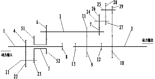
[0027] Such as figure 1 As shown, a transmission device for expanding the speed ratio range of the gearbox is characterized in that it includes a power input shaft 1, a power output shaft 2 and an intermediate shaft 3, and the power input shaft 1 and the power output shaft 2 are provided with a plurality of Gear driven gears, a gear synchronizer for realizing gear shifting is arranged between the multiple gears driven gears, and the gear driven gear of the highest gear among the multiple gears driven gears is set at On the end of the power input shaft 1 close to the power output shaft 2, the gear driven gears of each gear except the highest gear are arranged in the order of the gears from high to low along the direction of power output. On the power output shaft 2, the end of the power input shaft 1 away from the power output shaft 2 is provided with a power output driving gear 4, and the power between the gear driven gear of the highest gear and the power output driving gear ...

Embodiment 2

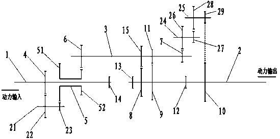
[0031] This embodiment is similar to Embodiment 1, the difference is that, as figure 2 As shown, the number of gear driven gears on the power input shaft 1 and the power output shaft 2 is four, which are respectively the fourth gear driven gear 14 on the power input shaft 1 and the gears on the power output shaft in turn. The third gear driven gear 8, the second gear driven gear 9 and the first gear driven gear 10 on the 2; The gear 8 and the third gear driving gear 15 and the second gear driving gear 11 meshed with the second gear driven gear 9; the number of the gear synchronizers is two, which are respectively located at the first gear driven gear 10 and the second gear. The first gear synchronizer 12 between the gear driven gears 9 and the second gear synchronizer 13 arranged between the third gear driven gear 8 and the fourth gear driven gear 14 . Other structures and working principles of this embodiment are the same as those of Embodiment 1.

Embodiment 3

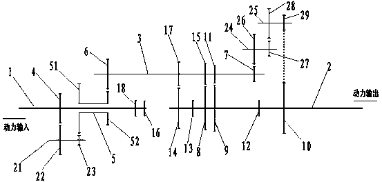
[0033] This embodiment is similar to Embodiment 1, the difference is that, as image 3 As shown, the number of gear driven gears on the power input shaft 1 and the power output shaft 2 is five, which are respectively the fifth gear driven gear 16 on the power input shaft 1 and the gears on the power output shaft in turn. The fourth gear driven gear 14 on the 2, the third gear driven gear 8, the second gear driven gear 9 and the first gear driven gear 10; the number of gear driving gears on the intermediate shaft 3 is three, respectively The fourth gear driving gear 17, the third gear driving gear 15 and the second gear driving gear 11 meshed with the fourth gear driven gear 14, the third gear driven gear 8 and the second gear driven gear 9; the gear synchronizer The number is three, which are the first gear synchronizer 12 arranged between the first gear driven gear 10 and the second gear driven gear 9, the third gear driven gear 8 and the fourth gear driven gear 9. The secon...


PUM


Abstract

The invention discloses a transmission device capable of widening a gearbox speed ratio range. The transmission device comprises a power input shaft, a power output shaft and an intermediate shaft; multi-gear driven gears are arranged on the power output shaft and the power input shaft; the gear driven gear at the highest gear is arranged on the power input shaft; the gear driven gears at the other gears are arranged on the power output shaft in sequence; the power input shaft is provided with a power output driving gear and an H gear; the power output driving gear is in transmission connection with a first gear of the H gear through a first multistage speed reducing structure; a first power output driven gear is arranged at one end of the intermediate shaft, and is engaged with a second gear of the H gear; a second power output driven gear is arranged at the other end of the intermediate shaft, and is in transmission connection with the gear driven gear at the lowest gear through a second multistage speed reducing structure; and the intermediate shaft is provided with gear driving gears correspondingly engaged with the gear driven gears at the rest gears besides of the lowest gearon the power output shaft.

Description

technical field [0001] The invention relates to the technical field of automobile transmission, and more specifically, relates to a transmission device for expanding the speed ratio range of a gearbox. Background technique [0002] In the use of automobiles, there are often special circumstances that require ultra-low reduction gears. It is hoped that the lowest gear ratio is greater than 10, while other gears are normally distributed in the range of 1-7, while ensuring intermediate gears other than direct gears and ultra-low gears It is also adjustable over the entire speed ratio range. In order to achieve this requirement, the existing technology often adopts gearboxes with more gears (addition of auxiliary boxes), such as eight-speed, nine-speed, ten-speed or even more than ten-speed gearboxes, while conventional six-speed gearboxes The design can't be realized. This will cause high manufacturing and use costs, especially in pure electric vehicles, because the variable ...

Claims


Application Information

Patent Timeline
Patent Type & Authority Applications(China)
IPC IPC(8): F16H3/32F16H61/26F16H61/70
CPCF16H3/32F16H61/26F16H61/707
Inventor 罗元月
Owner 韶关市广控机械传动技术有限公司
Why Eureka
Try Eureka