Hybrid power driving system and vehicle

A drive system and hybrid technology, applied in hybrid vehicles, engine-driven traction, motor vehicles, etc., can solve the problem of high cost, and achieve the effects of strong flexibility, simple overall structure, and reduced volume.

Pending Publication Date: 2020-09-29
GAC AION NEW ENERGY AUTOMOBILE CO LTD
View PDF0 Cites 1 Cited by
  • Summary
  • Abstract
  • Description
  • Claims
  • Application Information

AI Technical Summary

Problems solved by technology

However, the parallel hybrid system requires two independent subsystems, which is expensive and usually only used in weak hybrid systems

Method used


Image

  • Hybrid power driving system and vehicle
  • Hybrid power driving system and vehicle
  • Hybrid power driving system and vehicle

Examples


no. 1 example

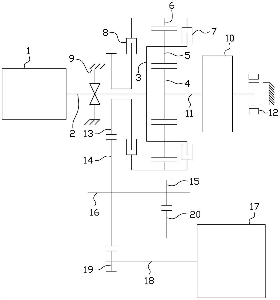
[0038] figure 1 is a schematic structural diagram of the hybrid drive system in the first embodiment of the present invention. like figure 1 As shown, the hybrid drive system of this embodiment includes an engine 1, a first shaft 2, a planetary row, a first clutch 7, a second clutch 8, a braking device 9, a generator 10, a second shaft 11, a brake 12, The first gear 13 , the second gear 14 , the third gear 15 , the third shaft 16 , the drive motor 17 , the fourth shaft 18 , the fourth gear 19 and the differential 20 . Wherein, the planet row includes a planet carrier 3 , a sun gear 4 , a planet gear 5 and a ring gear 6 .

[0039] The engine 1 is connected to the first shaft 2 , the generator 10 is connected to the second shaft 11 , and the driving motor 17 is connected to the fourth shaft 18 . Specifically, the first shaft 2 is the output shaft of the engine 1 , the second shaft 11 is the output shaft of the generator 10 , and the fourth shaft 18 is the output shaft of the ...

no. 2 example

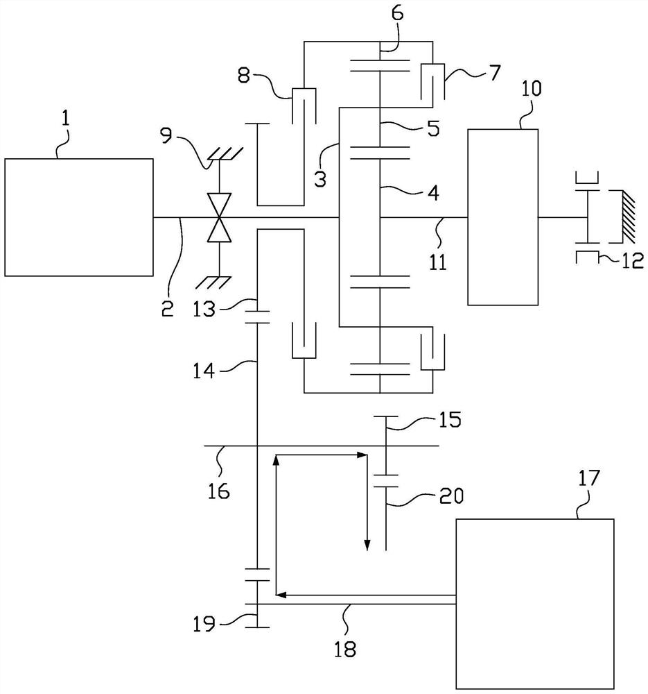
[0074] Figure 9 It is a schematic structural diagram of a hybrid drive system according to the second embodiment of the present invention. like Figure 9 As shown, the hybrid drive system of this embodiment is basically the same as that of the above-mentioned first embodiment, the only difference is that in this embodiment, the differential 20 meshes with the second gear 14, and the fourth gear 19 meshes with the third gear 15 meshes.

[0075] For other structures and working modes of this embodiment, reference may be made to the above-mentioned first embodiment, which will not be repeated here.

no. 3 example

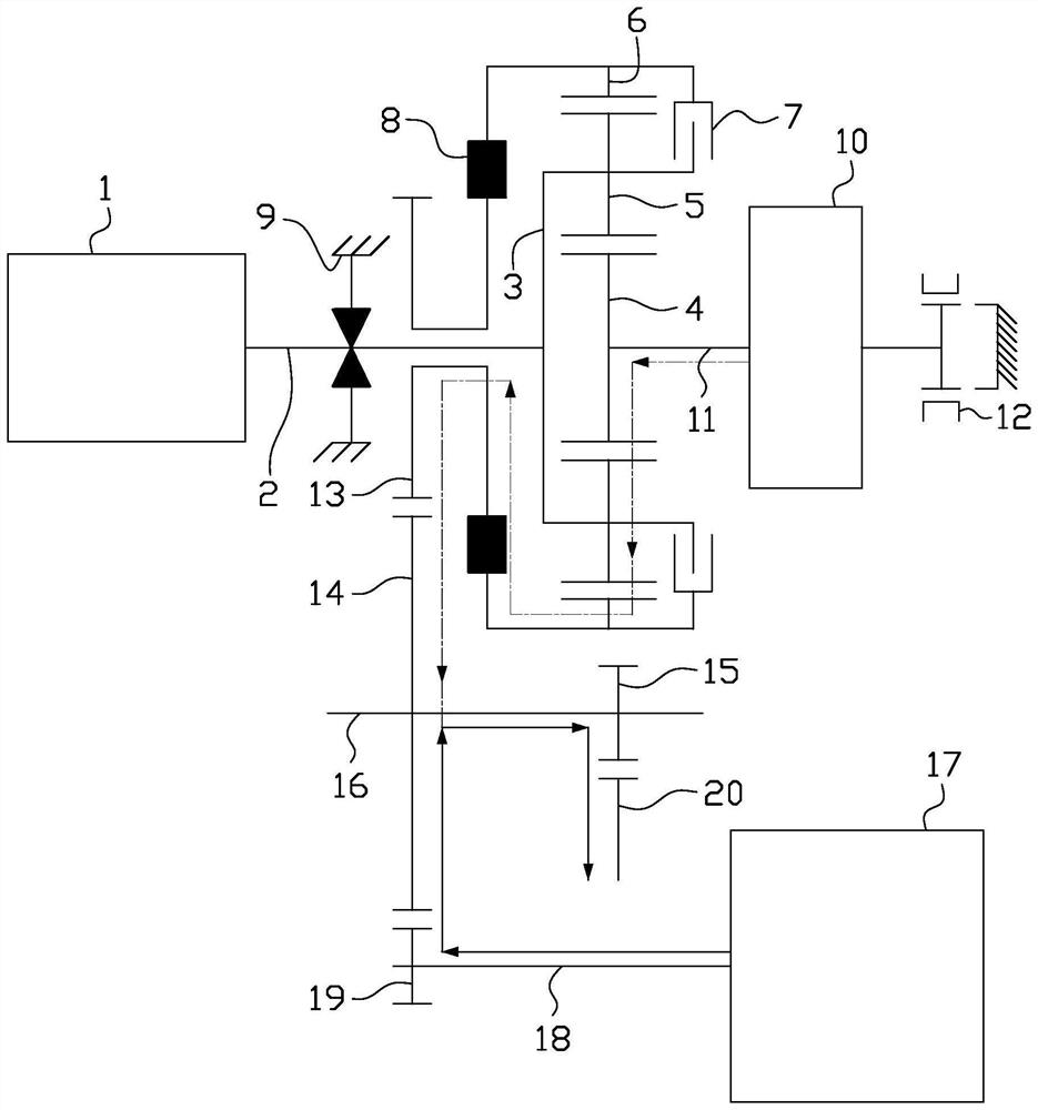
[0077] Figure 10 It is a schematic structural diagram of a hybrid drive system according to the third embodiment of the present invention. like Figure 10 As shown, the hybrid drive system of this embodiment is basically the same as that of the above-mentioned first embodiment, the only difference is that in this embodiment, the braking device 9 is specifically a brake. In the dual-motor pure electric mode, the engine 1 does not work, but the generator 10 outputs power. At this time, the brake works and brakes the first shaft 2 and the planet carrier 3, while in other modes, the brake does not work ( That is, the first shaft 2 and the planet carrier 3 are not braked).

[0078] For other structures and working modes of this embodiment, reference may be made to the above-mentioned first embodiment, which will not be repeated here.

[0079] Further, the present invention also provides a vehicle, including the above-mentioned hybrid drive system.


PUM


Abstract

The invention provides a hybrid power driving system. The hybrid power driving system comprises an engine, a first shaft, a planet row, a first clutch, a second clutch, a braking device, a generator,a second shaft, a brake, a first gear, a second gear, a third gear, a third shaft, a driving motor, a fourth shaft, a fourth gear and a differential mechanism. The hybrid power driving system is simple in structure, has multiple working modes and is good in platformization. The invention further provides a vehicle with the hybrid power driving system.

Description

technical field [0001] The invention relates to the field of new energy technologies, in particular to a hybrid drive system and a vehicle with the hybrid drive system. Background technique [0002] At present, there are two main types of transmissions on the market: stepped transmissions and continuously variable transmissions. Stepped transmissions are subdivided into manual and automatic. Most of them provide a limited number of discrete output and input speed ratios through different meshing arrangements of gear trains or planetary gear trains. The adjustment of the speed of the driving wheel between two adjacent speed ratios is This is achieved by means of speed changes of the internal combustion engine. Continuously variable transmission, whether mechanical, hydraulic or electromechanical, can provide an infinite number of continuously selectable speed ratios within a certain speed range. It can work in the best speed range as much as possible. Compared with the ste...

Claims


Application Information

Patent Timeline
IPC IPC(8): B60K6/445B60K6/46B60K6/365B60K6/38B60L50/15
CPCB60K6/365B60K6/38B60K6/445B60K6/46B60K2006/381Y02T10/62Y02T10/7072
Inventor 尚阳赵江灵祖国强杨洋任晓华
Owner GAC AION NEW ENERGY AUTOMOBILE CO LTD
Why Eureka
Try Eureka