
Rotor spinning method and device with four-sliver asynchronous input and three-stage carding

An asynchronous input, three-stage technology, applied in the direction of continuous winding spinning machine, spinning machine, open-end spinning machine, etc., can solve the problems of not given, blocked rotor cup, blocked carding roller, etc. Achieve the effects of longitudinal orientation optimization, good carding and transfer, and speed improvement

Active Publication Date: 2018-01-16
JIANGNAN UNIV
View PDF8 Cites 0 Cited by
  • Summary
  • Abstract
  • Description
  • Claims
  • Application Information

AI Technical Summary

Problems solved by technology

However, there are two problems in this invention: first, in the invention, it is only conceptually proposed that the mixed-color and segment-color spinning yarns with constant linear density can be realized by coupling drafting, and it is not given how to realize the constant linear density through coupling drafting. Changing the Mixing Ratio and Color Mixing Ratio
Simultaneously, specific implementation scheme and embodiment are not provided
Second, the patent application still uses a traditional single carding roller. When three cotton slivers are fed at the same time, the original carding and drafting system cannot fully complete the stripping, carding, mixing and decomposition of multiple cotton slivers. stretching, which will lead to insufficient decomposition of the fiber bundle, resulting in blocking of the opening roller and rotor cup, and the spinning is prone to defects such as end breaks, slubs, and neps.
The main problem is that the yarn density and blending ratio of the production line do not change, and the main problem is that two or more fibers cannot be blended in any proportion in the rotor spinning process.

Method used

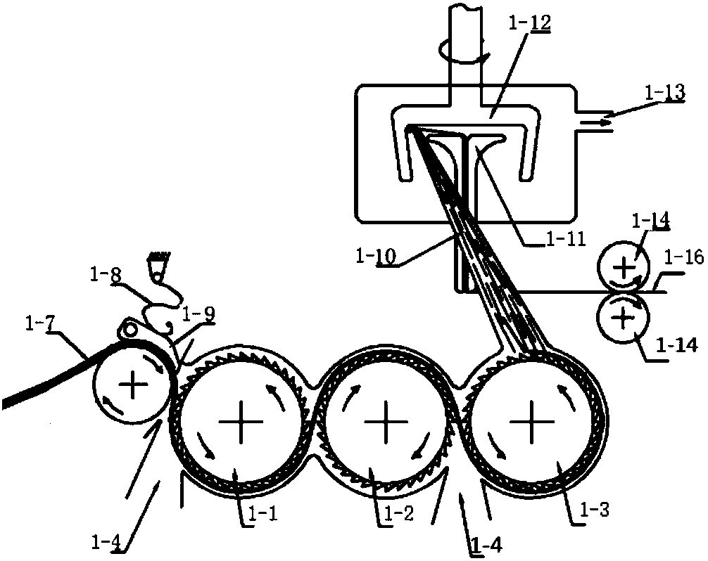
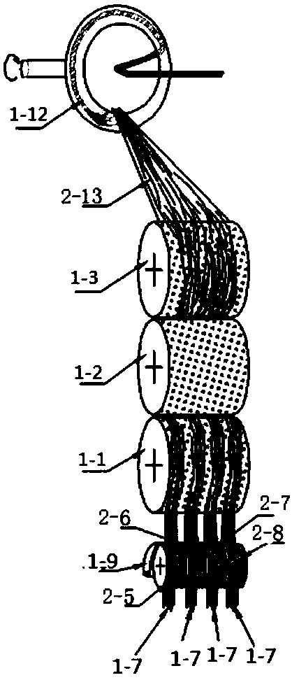
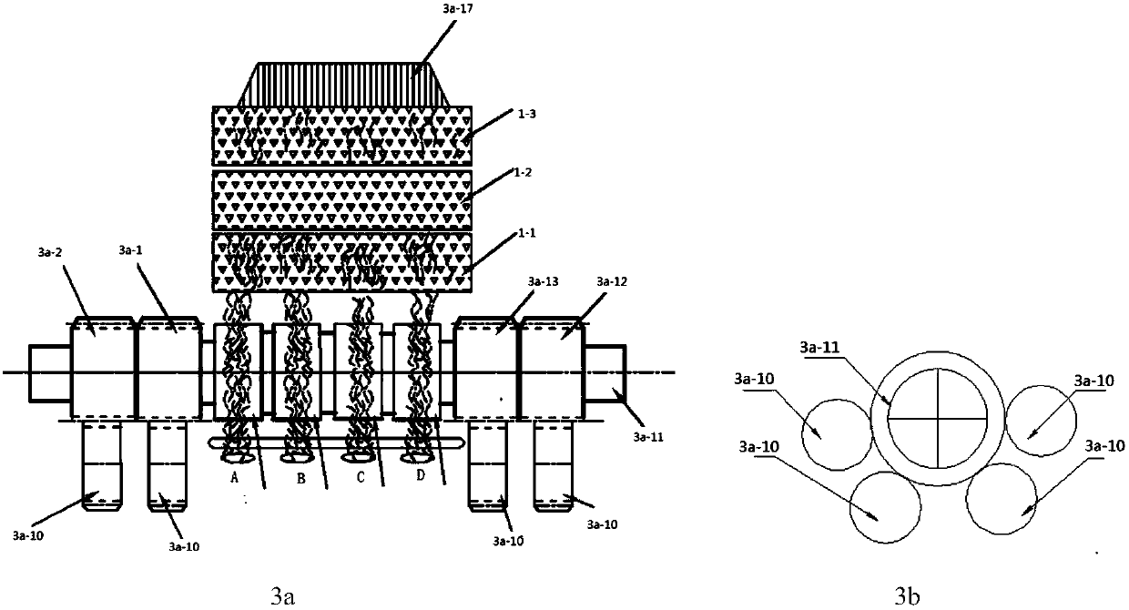

Image

  • Rotor spinning method and device with four-sliver asynchronous input and three-stage carding
  • Rotor spinning method and device with four-sliver asynchronous input and three-stage carding
  • Rotor spinning method and device with four-sliver asynchronous input and three-stage carding

Examples


Embodiment Construction

[0025] The meaning of the formula code used in the text:

[0026] V 01 : Linear speed of the first active roller; V 02 : linear speed of the second active roller; V 03 : Linear speed of the third active roller; V 04 : Linear speed of the fourth active roller; V 1 : linear speed of the first opening roller; V 2 : the linear speed of the second opening roller; V 3 : line speed of the third opening roller; V 4 : Linear speed of rotor; V 5 : Line speed of drawing roller;

[0027] ρ 1 : linear density of sliver A (g / m);

[0028] ρ 2 : linear density of sliver B (g / m);

[0029] ρ 3 : linear density of sliver C (g / m);

[0030] ρ 4 : linear density of sliver D (g / m);

[0031] ρ: Yarn density (g / m);

[0032] ρ 11 : the linear density (g / m) of sliver A passing through the first opening roller;

[0033] ρ 12 : the linear density (g / m) of sliver A through the second opening roller;

[0034] ρ 13 : the linear density (g / m) of sliver A through the third opening roller; ...


PUM


Abstract

A device for a multi-stage carding rotor spinning method, including a spinning system and a computer control system. The spinning system includes a feeding and carding mechanism, a cohesive twisting mechanism, and a winding forming mechanism. It is characterized in that the feeding and carding The mechanism includes a combined cotton feeding roller with four degrees of freedom in rotation and a multi-stage opening roller. The speed ratio of the four rollers of the combined cotton feeding roller with four degrees of freedom in rotation is adjustable, which realizes random control of rotor spinning. Yarn linear density and blending ratio.

Description

technical field [0001] The invention belongs to the field of rotor spinning in the textile industry Background technique [0002] The basic principle of rotor spinning yarn is: the cotton sliver is held by the cotton feeding plate and the cotton feeding roller from the bell mouth, and the cotton feeding roller rotates and transports the cotton sliver to the carding area; the carding roller pair rotating at high speed in the carding area The sliver is opened, stripped, combed, separated, and mixed to make it into single fibers that are separated from each other and arranged in parallel and enter the cotton conveying channel; Under the action of the centrifugal force of the cup, the fibers are further superimposed and mixed in the condensation tank, drawn out from the parent yarn and twisted by the twister to form a yarn. [0003] The patent "a method, device and product of rotor spinning mixed color yarn" (application number CN201410190891.1) and "a rotor spinning mixed colo...

Claims


Application Information

Patent Timeline
Patent Type & Authority Patents(China)
IPC IPC(8): D01H4/08D02G3/04D02G3/34
CPCD01H4/08D01H4/32D01H4/44
Inventor 高卫东薛元郭明瑞杨瑞华
Owner JIANGNAN UNIV
Learn More