Water cooling head

A water-cooled head, three-dimensional technology, applied in lighting and heating equipment, indirect heat exchangers, etc., can solve the difficulty of adding fins 22B', it is difficult to take into account the thermal conductivity of the base and the heat dissipation efficiency of the fins, etc.

Inactive Publication Date: 2018-07-20
AURAS TECH
View PDF4 Cites 3 Cited by
  • Summary
  • Abstract
  • Description
  • Claims
  • Application Information

AI Technical Summary

Problems solved by technology

[0005] However, since the function of the base 22' is to conduct heat energy into the cavity 23' of the water cooling head 2', the function of the fins 22B' is to increase more heat dissipation area in order to quickly transfer heat energy to the working fluid Therefore, the existing water cooling head 2' directly forms fins 22B' on the base 22'. It is difficult to take into account the thermal conductivity of the base and the heat dissipation performance of the fins at the same time, and if it is necessary to form a higher density and a larger heat dissipation area If the fin 22B' of the base is limited, it will also be limited by the original material of the base 22'
Furthermore, if the base 22' is not a complete plane, but Figure 1B If there is a circle of side walls 22C' extending toward the cover as shown, it will also increase the difficulty of forming fins 22B'

Method used


Image

  • Water cooling head
  • Water cooling head
  • Water cooling head

Examples


Embodiment Construction

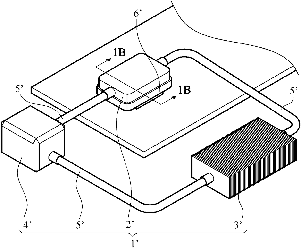
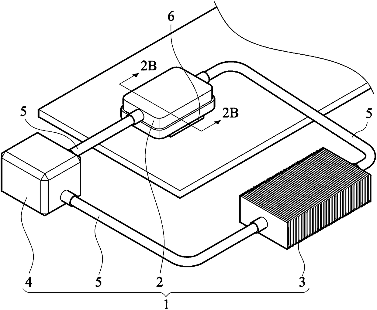
[0041] Figure 2A It is a three-dimensional schematic diagram of the water-cooling assembly proposed by an embodiment of the present invention. The water-cooling assembly 1 proposed in this embodiment is also composed of a water-cooling head 2, a water-cooling row 3, a pump 4 and a pipeline 5 to form a circulation path. The circulation path is filled with working fluid (not shown in the figure). When the water-cooling assembly 1 of this embodiment is in operation, the water-cooling head 2 will be in contact with the heat source 6 such as a chip, a memory or a light-emitting element, etc. At this time, the working fluid in the water-cooling head 2 will absorb the heat energy generated by the heat source 6 and The temperature is raised, and the temperature is lowered through the pipeline 5 to the water-cooled row 3 for heat exchange. Finally, the cooled working fluid will be sent back to the water-cooled head 2 for the next cycle. The water cooling assembly 1 may be provided wi...


PUM


Abstract

The invention provides a water cooling head. The water cooling head comprises a cover body, a base and a three-dimensional structural member. The base and the cover body together form a chamber, the three-dimensional structural member is disposed in the chamber, the side of the three-dimensional structural member is a plane, the plane is attached to the base, and the other side of the three-dimensional structural member is a fin. Therefore, the present invention can achieve both thermal conductivity of the base and heat dissipation of the fin, and is more elastic in the process.

Description

technical field [0001] The present invention relates to a water-cooled head, in particular to a water-cooled head whose base and fins are not integrally formed. Background technique [0002] Figure 1A It is a three-dimensional schematic diagram of an existing water-cooling assembly. The water cooling assembly 1' consists of a water cooling head 2' (Cold plate, also known as a cold plate), a water cooling row 3' (radiator, also known as a radiator), a pump 4' (pump) and a pipeline 5' to form a circulation path, and A working fluid (not shown) is filled in the circulation path. [0003] When the water-cooling assembly 1' is in operation, the water-cooling head 2' will be in contact with the heat source 6' such as a chip, a memory or a light-emitting element, etc. At this time, the working fluid in the water-cooling head 2' is absorbing the heat energy generated by the heat source 6' Afterwards, the temperature is raised, and the temperature is lowered by passing the pipelin...

Claims


Application Information

Patent Timeline
Patent Type & Authority Applications(China)
IPC IPC(8): F28D21/00
CPCF28D21/00
Inventor 吴安智范牧树陈建佑
Owner AURAS TECH
Why Eureka
Try Eureka