
Method for detecting shield channel influence area karst under building

A technology that affects areas and shield tunnels. It is applied in the field of karst detection. It can solve problems such as metal pipelines, electromagnetic interference, karst that cannot be effectively treated, and uneven settlement of buildings. It achieves strong low-frequency interference resistance and good social benefits. and economic benefits, enhancing the effect of feasibility

Active Publication Date: 2018-07-20
ZHONGJIAN SUIDAO CONSTR CO LTD +1
View PDF4 Cites 7 Cited by
  • Summary
  • Abstract
  • Description
  • Claims
  • Application Information

AI Technical Summary

Problems solved by technology

[0003] In actual engineering, drilling is usually used to detect karst development. Although the accuracy is the highest, it will significantly increase the project cost
In order to make the project more economical, karst detection is often carried out by drilling combined with geophysical prospecting to meet the construction accuracy requirements, such as cross-hole CT, geological radar, high-density electrical methods, etc. have been widely used; however, in In the case of important buildings, there are many metal pipelines and electromagnetic interference nearby, and drilling and conventional geophysical prospecting cannot be implemented due to site restrictions or the accuracy cannot meet the requirements. When karst development cannot be clearly detected, karst will not be effectively treated. , As a result, engineering accidents such as uneven settlement of buildings, surface deformation, tunnel water gushing, and shield machine heading are likely to be caused during the construction of the subway tunnel.

Method used


Image

  • Method for detecting shield channel influence area karst under building
  • Method for detecting shield channel influence area karst under building

Examples


Embodiment 1

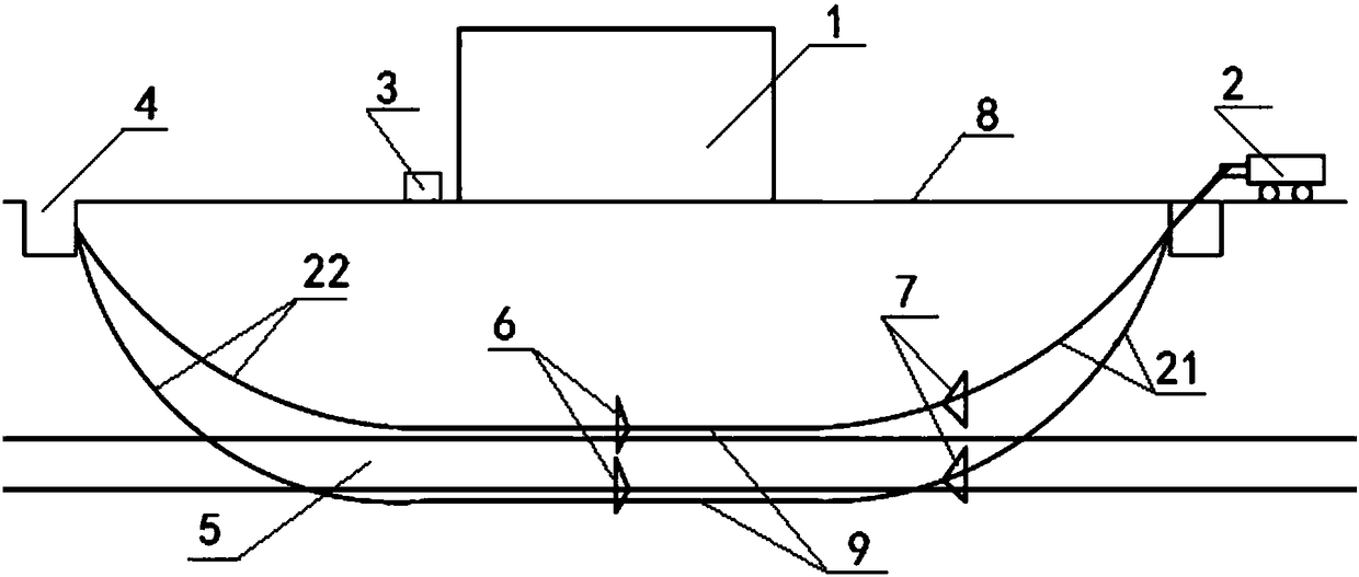
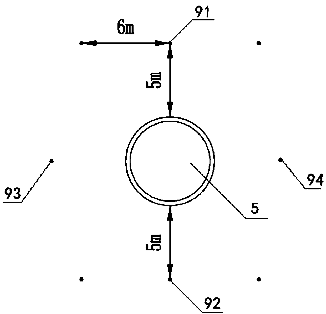
[0032] Such as figure 1 As shown, this embodiment provides a method for detecting karst in the affected area of ​​a shield tunnel under a building, including the following steps:

[0033] Step 1: Utilize the horizontal directional drilling machine 2 to drill holes horizontally around the tunnel 5 to be built;

[0034] Step 2: In the receiving well 4, the ultrasonic borehole imager 6 is dragged back across the borehole in the borehole as the sound source, and the cross-hole sound waves collected by the ultrasonic borehole imager 6 are collected by the data acquisition device 3 during the dragging process , forming CT input data;

[0035] Step 3: Perform acoustic tomography inversion on the CT input data, and use drawing software to display the cross-hole acoustic tomography map, and then based on the cross-hole acoustic wave velocity difference between the detection target and the surrounding rock of the detection target and the elastic wave propagation process The attenuatio...


PUM


Abstract

The invention discloses a method for detecting shield channel influence area karst under a building. A horizontal directional drilling machine is utilized to horizontally drill holes in the peripheryof a channel to be built, then in a receiving well, an ultrasonic wellbore imager performs cross-hole pullback in drill holes as an acoustic source, and cross-hole acoustic waves acquired by the ultrasonic wellbore imager are acquired through a data acquisition instrument to form CT input data; and acoustic wave tomographic inversion is performed on the CT input data, mapping software is utilizedto display a cross-hole acoustic wave tomographic map, and finally, a karst distribution situation in a channel range under the building is analyzed based on acoustic wave velocity difference of a detection target and surrounding rock thereof and an attenuation law in an elastic wave propagation process. The karst detection method can overcome limitation of site conditions, an anti-interference capability is high, detection precision and resolution are high, a karst development situation in the subway tunnel range under the building can be precisely detected, risks of construction of the tunnel underneath passing the building are reduced, and the method has good social benefits and economic benefits.

Description

technical field [0001] The invention relates to the technical field of karst detection, in particular to a karst detection method in the area affected by a shield tunnel under a building. Background technique [0002] my country's rail transit has entered a stage of rapid development in recent years, and the construction of subways has been fully rolled out in major cities. However, while the number of subway lines continues to increase, it is unavoidable that the lines pass through buildings. In the karst-developed area, karst has a great impact on the subway passing through buildings. Detection plays a very important role in ensuring the safety of tunnel construction. [0003] In actual engineering, drilling is usually used to detect the development of karst. Although the accuracy is the highest, it will significantly increase the project cost. In order to make the project more economical, karst detection is often carried out by drilling combined with geophysical prospec...

Claims


Application Information

Patent Timeline
Patent Type & Authority Applications(China)
IPC IPC(8): G01V1/00
CPCG01V1/00
Inventor 张可能钟志全穆岩松贺湘东刘湛张云毅陈泽李江灵朱考飞马晓磊
Owner ZHONGJIAN SUIDAO CONSTR CO LTD
Learn More