Coating roller for multi-pole battery coating machine and coating method for multi-pole battery pole piece

A technology for battery pole pieces and coating methods, which is applied to battery electrodes, devices for coating liquid on the surface, secondary batteries, etc., can solve problems such as puncture, affect safety performance, and affect battery capacity, and increase the dressing area , high safety performance and high coating efficiency

Pending Publication Date: 2018-07-24
OPTIMUM BATTERY CO LTD
View PDF0 Cites 6 Cited by
  • Summary
  • Abstract
  • Description
  • Claims
  • Application Information

AI Technical Summary

Problems solved by technology

[0003] When the existing coating machine coats the multi-tab battery, the coating roller rotates to drive the slurry, and the slurry is transferred to the base material of the pole piece by the rotation of the back roller, and the back roller of the coating machine will Intermittent pop-up to meet the requirements of the coating gap of multi-pole tabs. This coating method has low coating efficiency and will cause problems such as tailing, gap misalignment, no material in the gap, and too large area; at the same time, multiple Since the tab cylindrical lithium-ion battery has multiple tabs in the positive and negative plates, and the tab is in the middle of the winding core, during the charge and discharge process, because the position of the tab of the negative electrode cannot carry out lithium insertion, the negative electrode will appear during the cycle. The phenomenon of serious lithium deposition at the tab position affects the capacity of the battery. Severe lithium deposition can lead to the generation of lithium dendrites, which can pierce the battery diaphragm and seriously affect the safety performance of the battery. Deep lithium deposition at the tab position can also lead to extreme Ear position fragments seriously affect safety performance

Method used


Image

  • Coating roller for multi-pole battery coating machine and coating method for multi-pole battery pole piece
  • Coating roller for multi-pole battery coating machine and coating method for multi-pole battery pole piece
  • Coating roller for multi-pole battery coating machine and coating method for multi-pole battery pole piece

Examples


Embodiment Construction

[0022] In order to make the object, technical solution and beneficial technical effects of the present invention clearer, the present invention will be further described in detail below in conjunction with the accompanying drawings and specific embodiments. It should be understood that the specific implementations described in this specification are only for explaining the present invention, not for limiting the present invention.

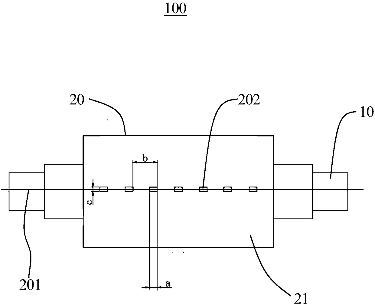
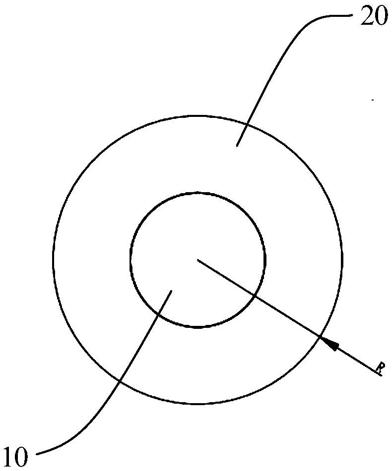
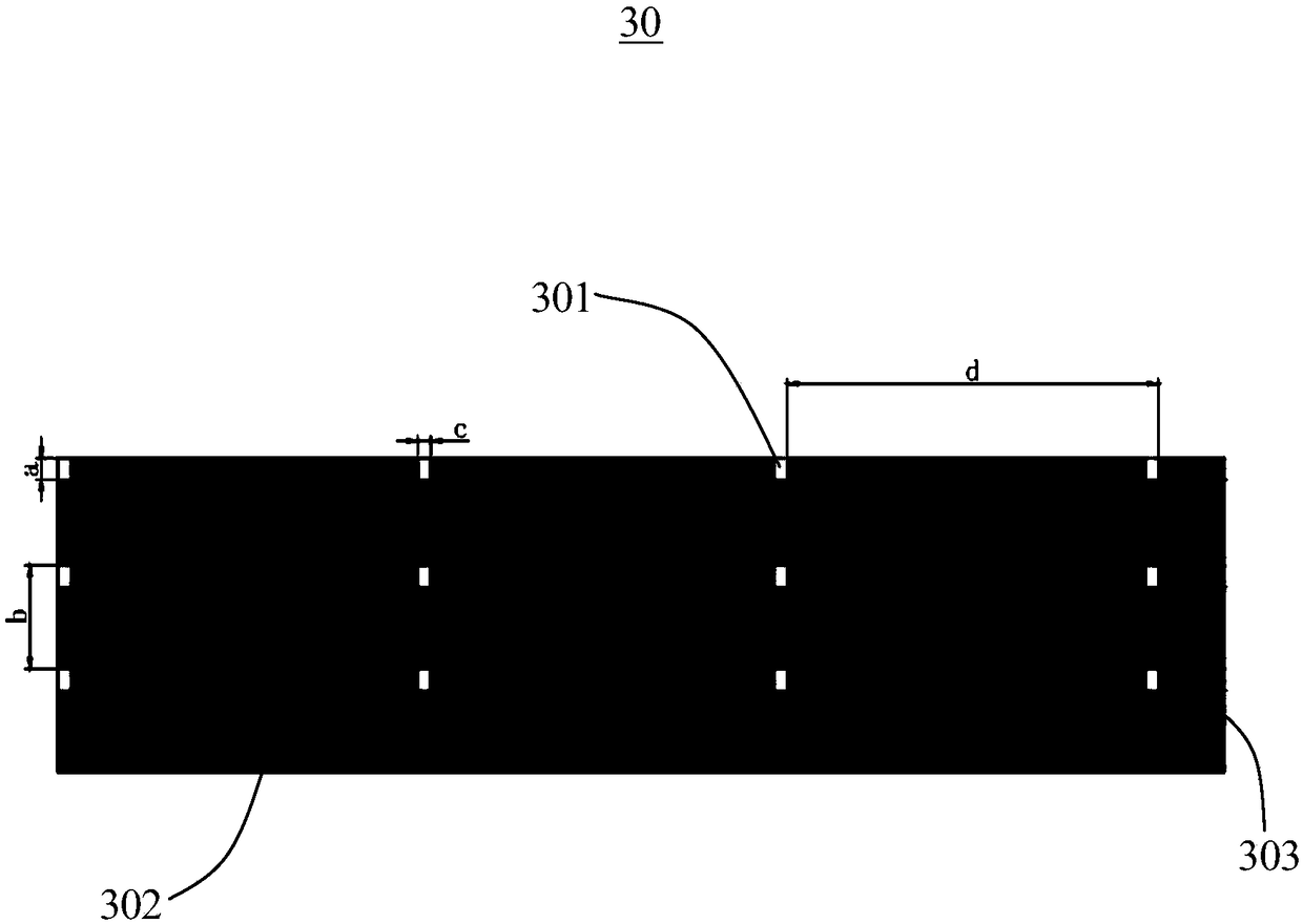
[0023] see figure 1 and figure 2 , the present invention provides a coating roller 100 for a multi-tab battery coating machine, comprising a rotating shaft 10 and a coating roller body 20; the coating roller body 20 is sleeved on the rotating shaft 10 and rotates around the rotating shaft 10, so The coating roller body 20 is cylindrical and has a central axis 201. The outer peripheral wall 21 of the coating roller body 20 is recessed toward the direction close to the central axis 201 to form a plurality of grooves 202, and the plurality of groove...


PUM

PropertyMeasurementUnit
thicknessaaaaaaaaaa
widthaaaaaaaaaa
thicknessaaaaaaaaaa

Abstract

The invention provides a coating roller for a multi-pole battery coating machine. The coating roller comprises a rotating shaft and a coating roller body. The rotating shaft is sleeved with the coating roller body and the coating roller body rotates around the rotating shaft. The coating roller body is in a cylindrical shape and is provided with a central shaft, and a plurality of grooves is formed in the outer peripheral wall of the coating roller body in the direction closing to the central shaft. The multiple grooves are arranged side by side in the direction of the central shaft. The invention further discloses a coating method for a multi-pole battery pole piece. According to the coating roller for the multi-pole battery coating machine and the coating method for the multi-pole battery pole piece, a backing roll does not need to be intermittently flicked, and the continuous coating of the coating machine is realized, the coating efficiency is high, the dressing area of the pole edge is increased, the lithium precipitation at the pole of a negative electrode is prevented, and the safety performance is high.

Description

【Technical field】 [0001] The invention relates to the technical field of battery materials, in particular to a coating roller of a multi-tab battery coating machine and a coating method for multi-tab battery pole pieces. 【Background technique】 [0002] Cylindrical lithium-ion batteries are widely used in the electronic field due to their high production consistency and high safety; and, with the development of electric vehicles, electric tools, and electric model aircraft, people are concerned about the energy density and rate discharge of cylindrical batteries and The temperature rise of the discharge puts forward higher requirements, the diameter of the battery increases accordingly, and the length of the positive and negative electrodes of the battery increases. If a single tab is used, the internal resistance of the battery will be very large, and the polarization of the battery will Seriously, it affects the service life and safety performance of the battery. Therefore,...

Claims


Application Information

Patent Timeline
Patent Type & Authority Applications(China)
IPC IPC(8): B05C1/08B05D1/28H01M4/04H01M10/0525
CPCB05C1/08B05C1/0808B05D1/28H01M4/0409H01M10/0525Y02E60/10
Inventor 王洪湖王海涛许辉李路伟李金林
Owner OPTIMUM BATTERY CO LTD
Why Eureka
Try Eureka