Conveniently-mounted invisible anti-theft net

A technology that is easy to install and anti-theft net, applied in the direction of fixed grille, etc., can solve the problems of heavy workload, troublesome installation, and ineffectiveness of anti-theft net.

Inactive Publication Date: 2018-07-24
李堂波
View PDF6 Cites 4 Cited by
  • Summary
  • Abstract
  • Description
  • Claims
  • Application Information

AI Technical Summary

Problems solved by technology

[0005] Although the above technical solutions can play the role of anti-theft, when installing, two steel wires need to be wound on the upper bracket and the lower bracket in turn, the workload is large, and the installation is troublesome, and once the two steel wires are all broken or loose, it will cause The entire anti-theft net loses its function, and it is very troublesome to replace the steel wire

Method used


Image

  • Conveniently-mounted invisible anti-theft net
  • Conveniently-mounted invisible anti-theft net
  • Conveniently-mounted invisible anti-theft net

Examples


Embodiment 1

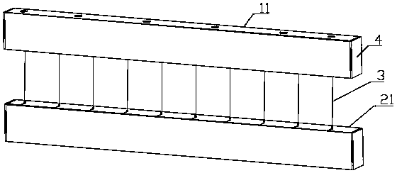
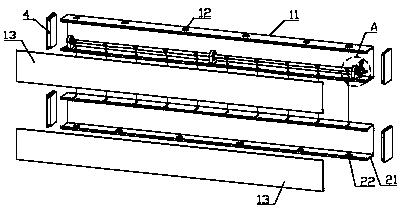
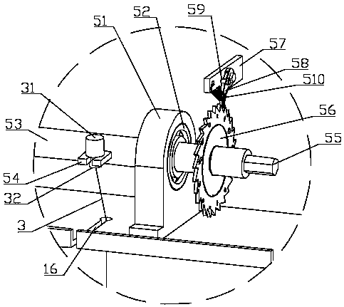
[0037] like Figure 1 to Figure 7 and Figure 12 , Figure 13As shown in the figure, an invisible anti-theft net for easy installation of the present invention includes an upper frame body 11, a lower frame body 21 and a steel wire 3, the upper frame body 11 is provided with an upper mounting hole 12 at the top, and the upper frame body 11 is provided with a first Slot 16, a tensioning mechanism is installed in the upper frame body 11; a lower mounting hole 22 is opened at the bottom of the lower frame body 21, a lower threading hole and a second slot are opened at the top of the lower frame body 21, and the lower threading hole is communicated with the second slot; The steel wire 3 passes through the first gap 16 and the second gap, the upper end of the steel wire 3 is connected to the tensioning mechanism, the lower end of the steel wire 3 is connected to the lower frame 21, the tensioning mechanism includes at least two bearing seats 51, and the bearing seats 51 are instal...

Embodiment 2

[0044] like Figures 8 to 13 As shown, the difference between this embodiment and the first embodiment is that the tensioning mechanism includes at least two screws 61, the screws 61 are connected between the upper and lower side walls of the upper frame 11, and the screws 61 are A connecting plate 62 is slidably connected, the connecting plate 62 is provided with a second upper threading hole and a fourth slit, the second upper threading hole is communicated with the fourth slit, an adjusting nut 63 is connected to the screw 61, and the adjusting nut 63 is close to the connecting plate On the lower surface of 62, the upper end of the steel wire 3 is connected with the second cylinder head 32, the upper end of the second cylinder head 32 is connected with the first cylinder head 31, the second cylinder head 32 is inserted into the second upper threading hole, and the first cylinder head 31 is close to the On the connecting plate 62, the lower end of the steel wire 3 is connect...


PUM


Abstract

The invention belongs to the technical field of security and protection facilities, and particularly relates to a conveniently-mounted invisible anti-theft net. The conveniently-mounted invisible anti-theft net comprises an upper frame body, a lower frame body and steel wires; upper mounting holes are formed in the top of the upper frame body, first gaps are formed in the bottom of the upper framebody, and a tensioning mechanism is mounted in the upper frame body; lower mounting holes are formed in the bottom of the lower frame body, lower threading holes and second gaps are formed in the topof the lower frame body, and the lower threading holes communicate with the second gaps; and the steel wires penetrate through the first gaps and the second gaps, the upper ends of the steel wires are connected with the tensioning mechanism, and the lower ends of the steel wires are connected with the lower frame body. The mounting process is simple and quick, in the using process, when one certain steel wire is broken or loosened, other steel wires can still achieve the protection effect, and in addition, steel wire replacement is also very easy and convenient.

Description

technical field [0001] The invention belongs to the technical field of security facilities, in particular to an invisible anti-theft net that is convenient to install. Background technique [0002] Invisible anti-theft net is a kind of anti-theft net used for protection and anti-fall. It is not invisible, but is wound by a 2MM thick steel wire between the profiles fixed at the outer end of the window. It can withstand a pulling force of more than 85-120KG, which can ensure that thieves cannot tear it off. Because there is a 5CM distance between the steel wires, it is impossible for people to drill into the gap, so it can effectively play the role of anti-theft protection. [0003] The invisible anti-theft net is specially designed with the wire cutting alarm function. When the thief cuts the wire, the intelligent alarm connected to the steel wire will send out an alarm siren. The alarm will be carried out in two ways at the same time. Tweets can effectively scare off thieve...

Claims


Application Information

Patent Timeline
Patent Type & Authority Applications(China)
IPC IPC(8): E06B9/01
CPCE06B9/01E06B2009/015
Inventor 李堂波
Owner 李堂波
Why Eureka
Try Eureka