
Rotor test bench support position adjustment and bearing pre-tightening device

A technology for test benches and bearings, applied in the direction of shafts and bearings, bearing components, rigid supports of bearing components, etc., can solve problems such as difficulty in ensuring speed margin, threat to operator safety, and reduction of external force of supports, achieving cost savings Low, enhance the expansion, reduce the effect of supporting external force

Active Publication Date: 2020-01-03
SOUTHEAST UNIV
View PDF4 Cites 0 Cited by
  • Summary
  • Abstract
  • Description
  • Claims
  • Application Information

AI Technical Summary

Problems solved by technology

[0002] At present, the design of the aero-engine simulation rotor test bench adopts the criterion of "ensure that there is sufficient margin between the operating speed and the critical speed". and gyro torque, the rolling body of the bearing will deviate from the original position, and the stiffness of the bearing will change significantly, so it is difficult to guarantee the "rotational speed margin" in the design, and the rotational speed of the rotor will be close to the critical rotational speed. The load will be transmitted to the support through the bearing, which will cause the rotor test bench to vibrate violently, causing damage to the rotor test bench and posing a threat to the safety of the operator. Therefore, after installation, it is necessary to adjust the structural parameters of the test bench so that the working speed and the critical speed There is enough margin to reduce the external force of the support, so it is important to arrange the support position reasonably and improve the stiffness of the bearing under working conditions

Method used


Image

  • Rotor test bench support position adjustment and bearing pre-tightening device
  • Rotor test bench support position adjustment and bearing pre-tightening device
  • Rotor test bench support position adjustment and bearing pre-tightening device

Examples


Embodiment Construction

[0016] The technical solution of the present invention will be further described below in conjunction with the accompanying drawings.

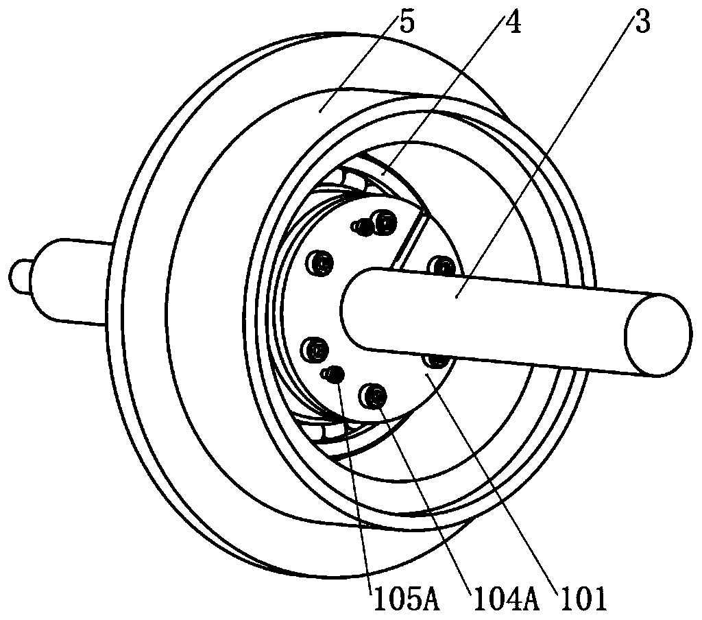
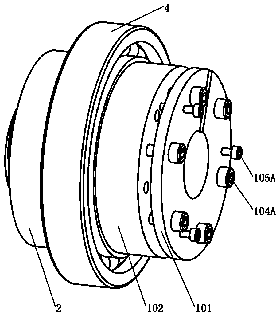
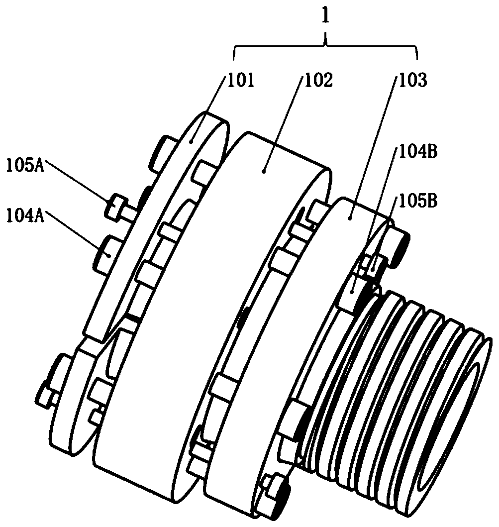
[0017] Such as Figure 1-7 As shown, a rotor test bench support adjustment and bearing pretensioning device includes a shaft 3, a support adjustment assembly 1 and a preload assembly 2, wherein the support adjustment assembly 1 includes a first coupling sleeve 101, a second coupling sleeve 102 and the third coupling sleeve 103, the pretensioning assembly 2 includes the pretensioning sleeve 201 and the spring 202; the shaft 3 is covered with the first coupling sleeve 101 and the second coupling sleeve 102, the first coupling sleeve 101 and the second coupling sleeve 102 are both It is disc-shaped and protrudes forward from the conical cylinder. The conical cylinder of the first coupling sleeve 101 is placed in the conical cylinder of the second coupling sleeve 102. The two cooperate with each other and the disc of the first coupling sleeve 101 ...


PUM


Abstract

The invention discloses a support positioning and bearing pre-tightening device for a rotor experiment table. The support positioning and bearing pre-tightening device comprises a shaft. The shaft issleeved with a first linkage sleeve and a second linkage sleeve. The first linkage sleeve and the second linkage sleeve are each in a disc shape and extend forwards to form a conical barrel. The conical barrel of the first linkage sleeve is arranged in the conical barrel of the second linkage sleeve. The conical barrel of the first linkage sleeve is matched with the conical barrel of the second linkage sleeve, and a disc of the first linkage sleeve and a disc of the second linkage sleeve are fixedly connected together. The conical barrel of the second linkage sleeve is sleeved with a ringlikethird linkage sleeve. The third linkage sleeve and the disc of the second linkage sleeve are fixedly connected together. The outer surface of the second linkage sleeve is provided with a thread. A pre-tightening sleeve is screwed on the thread. A bearing is fixedly connected to the outer surface of the third linkage sleeve. The support positioning and bearing pre-tightening device has the beneficial effects that the support position is reasonably arranged, and a bearing is pre-tightened, so that the support outbound force is reduced; vibration of the rotor experiment table is reduced; and working performance of the rotor experiment table and safety achieved in the working state are improved.

Description

technical field [0001] The invention relates to a support position adjustment and bearing pre-tightening device, in particular to a support position adjustment and bearing pre-tightening device of a rotor test bench. Background technique [0002] At present, the design of the aero-engine simulation rotor test bench adopts the criterion of "ensure that there is sufficient margin between the operating speed and the critical speed". and gyro torque, the rolling body of the bearing will deviate from the original position, and the stiffness of the bearing will change significantly, so it is difficult to guarantee the "rotational speed margin" in the design, and the rotational speed of the rotor will be close to the critical rotational speed. The load will be transmitted to the support through the bearing, which will cause the rotor test bench to vibrate violently, causing damage to the rotor test bench and posing a threat to the safety of the operator. Therefore, after installati...

Claims


Application Information

Patent Timeline
Patent Type & Authority Patents(China)
IPC IPC(8): F16C35/073
CPCF16C35/073
Inventor 费庆国何俊增张大海柳友志刘璟泽
Owner SOUTHEAST UNIV
Learn More