A semi-automatic tool measuring angle table device
What is Al technical title?
Al technical title is built by PatSnap Al team. It summarizes the technical point description of the patent document.
A semi-automated, bench-mounted device technology, applied in the direction of angle/taper measurement, can solve the problems of low measurement efficiency and poor measurement accuracy, and achieve the effect of improved measurement efficiency, reasonable structure and close contact
Active Publication Date: 2020-01-21
ZHONGBEI UNIV
View PDF10 Cites 0 Cited by
Summary
Abstract
Description
Claims
Application Information
AI Technical Summary
This helps you quickly interpret patents by identifying the three key elements:
Problems solved by technology
Method used
Benefits of technology
Problems solved by technology
[0003] In order to solve the problems of low measurement efficiency and poor measurement accuracy of the existing turning tool angle measuring table, the present invention provides a semi-automatic tool angle measuring table device
Method used
Image
Click on the blue label to locate the original text in one second.
Reading with bidirectional positioning of images and text.
Examples
Embodiment Construction
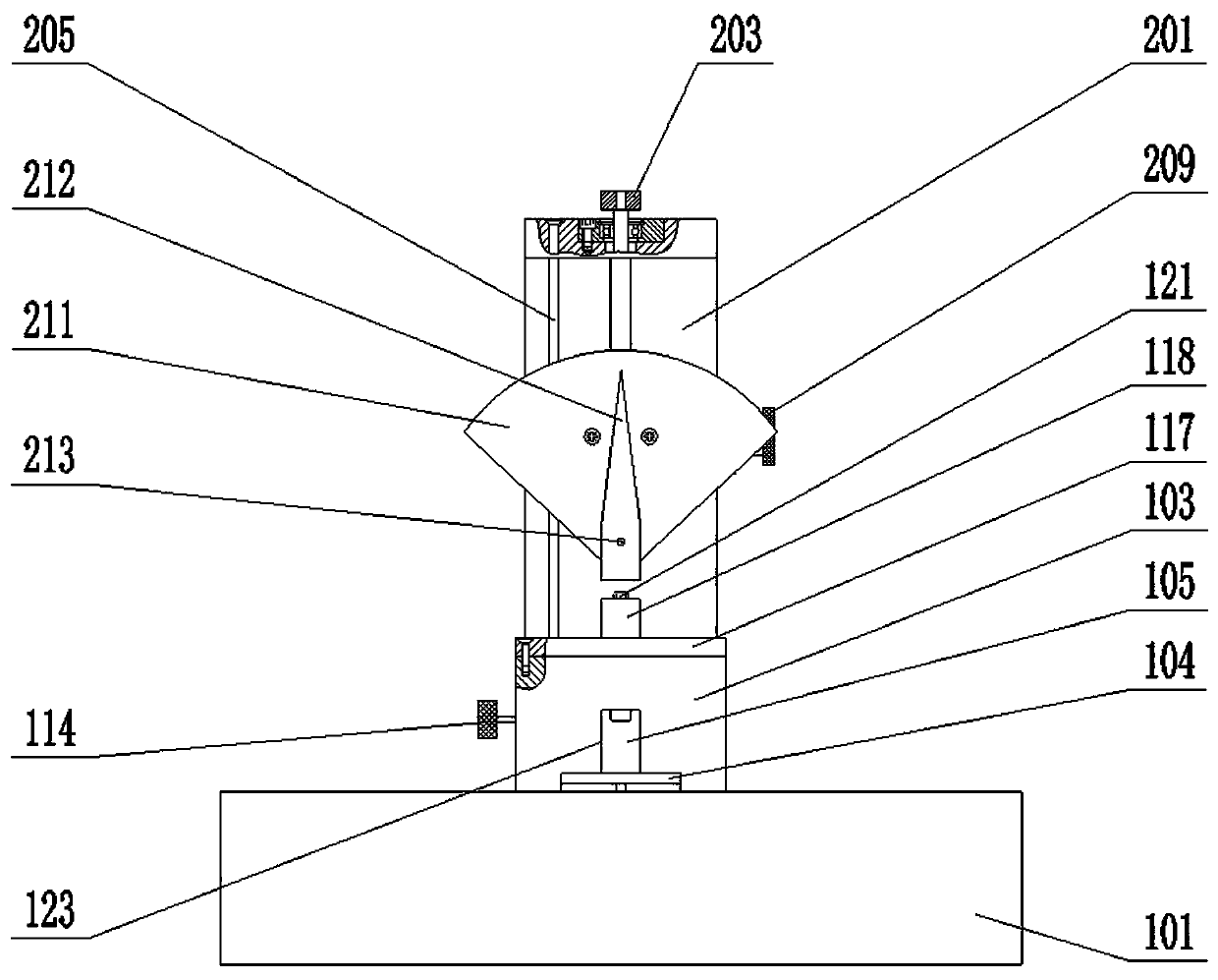
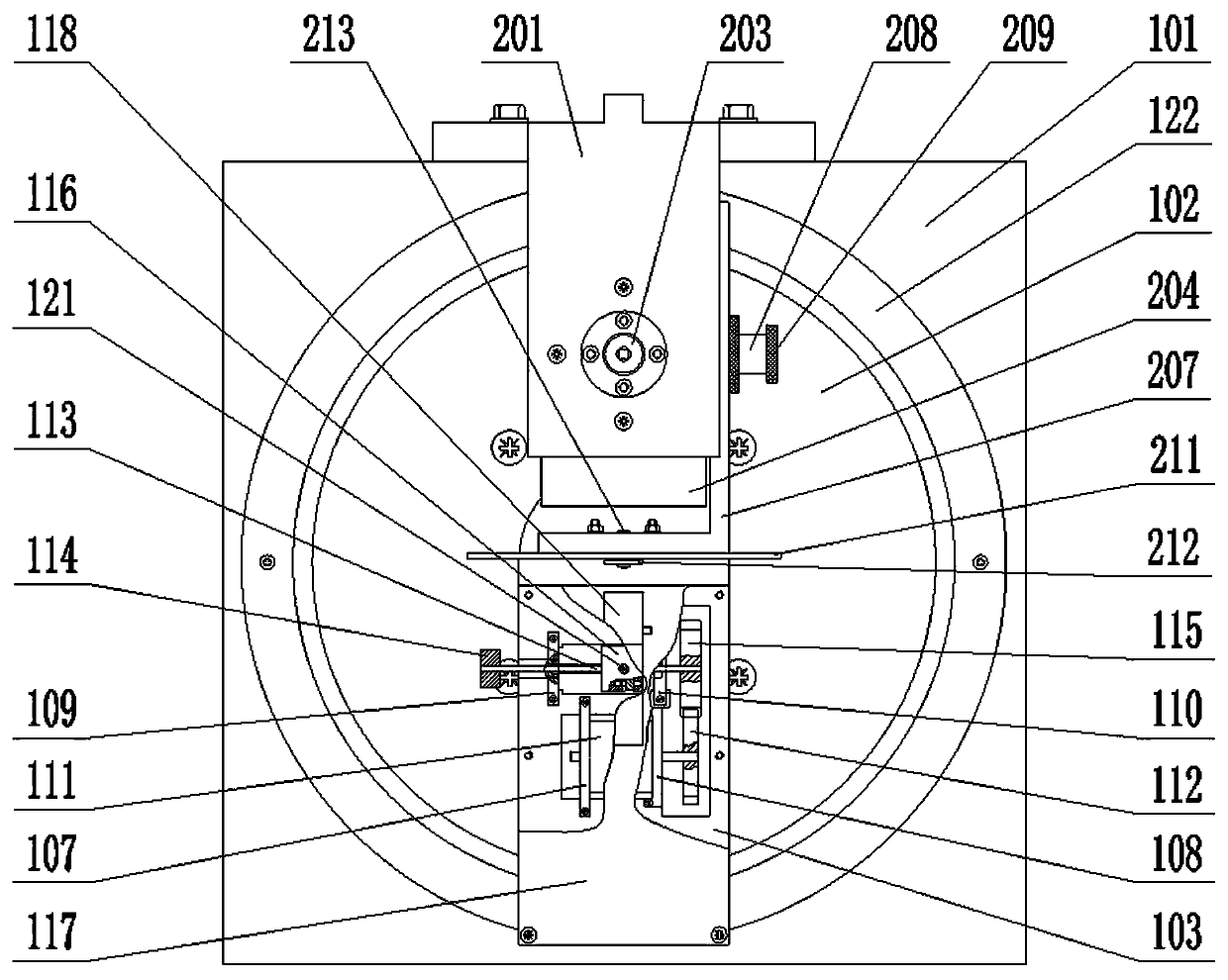
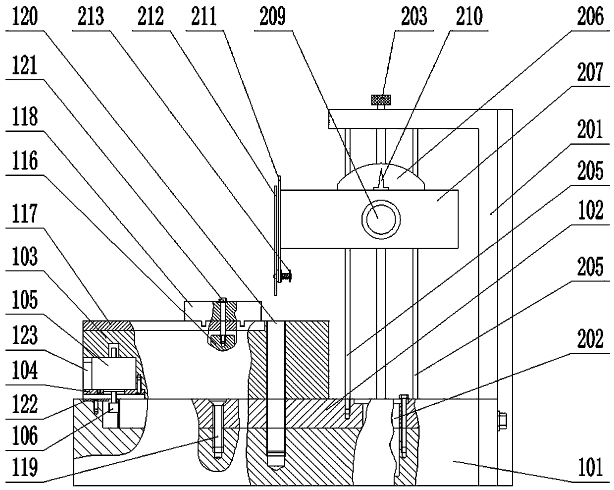
[0017] A semi-automatic tool measuring angle table device, including a support part and a measuring part;
[0018] Described support part comprises base platform 101, fixed gear 102, rotating platform 103, horizontal baffle plate 104, the 1st stepper motor 105, rolling gear 106, the 1st vertical baffle plate 107, the 2nd vertical baffle plate 108 , the III vertical baffle plate 109, the IV vertical baffle plate 110, the II stepping motor 111, driving gear 112, horizontal screw mandrel 113, the I knob 114, driven gear 115, slide seat 116, horizontal panel 117 , traverse platform 118, vertical screw 119, vertical screw rod 120, vertical bolt 121;
[0019] The upper table of the base platform 101 is provided with a disc-shaped concave cavity; the upper table of the base platform 101 is marked with a circular scale, and the circular scale surrounds the outside of the disc-shaped concave cavity; The front part of the bottom is provided with the first threaded concave hole; the cen...
PUM
Abstract
The invention relates to a lathe tool measuring angle bench and especially relates to a semi-automatic cutter measuring angle bench device. In the invention, problems that the measurement efficiency of an existing lathe tool measuring angle bench is low and measurement precision is poor are solved. The semi-automatic cutter measuring angle bench device comprises a supporting seat portion and a measurement portion. The supporting seat portion comprises a pedestal platform, a fixed gear, a rotating platform, a horizontal baffle plate, a first stepping motor, a rolling gear, a first vertical baffle plate, a second vertical baffle plate, a third vertical baffle plate, and a fourth vertical baffle plate, a second stepping motor, a driving gear, a transverse screw rod, a first rotation knob, a driven gear, a slide seat, a horizontal panel, a traverse moving platform, a vertical screw, a vertical threaded rod and a vertical bolt. The measurement portion comprises an L-shaped fixing plate, a screw-rod stepping motor, a second rotation knob, a lifting platform, a guiding stand column, a small dial, an L-shaped lifting plate, a transverse threaded rod, a third rotation knob, a small finger degree sheet, a large dial, a large finger degree sheet and a mutual-inserted rivet. The device is suitable for lathe tool angle measuring.
Description
technical field [0001] The invention relates to a turning tool angle measuring table, in particular to a semi-automatic tool angle measuring table device. Background technique [0002] The turning tool angle measuring table is widely used in the teaching and experiment of engineering colleges, and its function is to measure the angle of the turning tool. Due to the limitation of its own structure, the existing turning tool angle table needs manual operation to measure, so it generally has the problems of low measurement efficiency and poor measurement accuracy. Based on this, it is necessary to invent a new turning tool angle measuring platform to solve the problems of low measurement efficiency and poor measurement accuracy of the existing turning tool angle measuring platform. Contents of the invention [0003] In order to solve the problems of low measurement efficiency and poor measurement accuracy of the existing turning tool angle measuring platform, the invention p...
Claims
Application Information
Patent Timeline
Application Date:The date an application was filed.
Publication Date:The date a patent or application was officially published.
First Publication Date:The earliest publication date of a patent with the same application number.
Issue Date:Publication date of the patent grant document.
PCT Entry Date:The Entry date of PCT National Phase.
Estimated Expiry Date:The statutory expiry date of a patent right according to the Patent Law, and it is the longest term of protection that the patent right can achieve without the termination of the patent right due to other reasons(Term extension factor has been taken into account ).
Invalid Date:Actual expiry date is based on effective date or publication date of legal transaction data of invalid patent.