Visual field monitoring system and method with photo management function

A technology of on-site monitoring and management functions, applied in the field of visual on-site monitoring system, can solve the problems of management omissions, non-integration, 3D model and real scene visualization technology, etc., to achieve the effect of improving accuracy, improving progress control, and improving experience

Inactive Publication Date: 2018-07-24
安徽博诺思信息科技有限公司
View PDF7 Cites 1 Cited by
  • Summary
  • Abstract
  • Description
  • Claims
  • Application Information

AI Technical Summary

Problems solved by technology

[0002] Most of the traditional construction management information systems are based on the needs of project management, and the project management streams that are circulated online are developed based on the visual site monitoring system processes and forms with photo management functions, which cannot be automatically and real-time collected or directly and automatically extracted from the system. The visual on-site monitoring system with photo management function does not use 3D model and real-scene visualization technology, nor is it integrated into a unified information platform, and cannot have a visual on-site monitoring system with photo management function. Provide effective decision support for engineers
[0003] In the existing technology, management personnel are often used to visit each job to control the operation. It is understood that this will cause too many management personnel, and relying solely on management personnel to control will cause management omissions

Method used


Image

  • Visual field monitoring system and method with photo management function
  • Visual field monitoring system and method with photo management function

Examples


Embodiment Construction

[0034] In order to make the purpose, technical solution and advantages of the invention clearer, the technical solution of the present invention will be further described in detail below through the accompanying drawings and embodiments. However, it should be understood that the specific embodiments described here are only used to explain the technical solution of the present invention, and are not intended to limit the scope of the technical solution of the present invention.

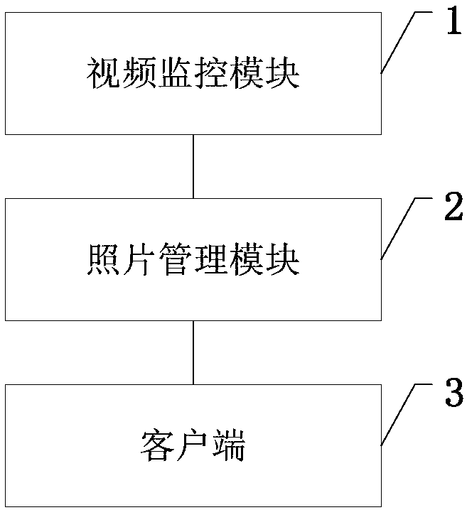
[0035] In order to solve the existing technical problems, the embodiment of the present invention provides a visual on-site monitoring system with photo management function, such as figure 1 As shown, video monitoring module 1, photo management module 2 and client 3;

[0036] The video monitoring module 1 is used to be connected to the photo management module 2, and is connected to the photo management module 2, and is used to send photos to the photo management module 2; the photo management module 2 ...


PUM


Abstract

The invention discloses a visual field monitoring system with a photo management function. The system comprises a video monitoring module, a photo management module and a client. The video monitoringmodule is used for connecting the photo management module. The video monitoring module is connected to the photo management module and is used for sending photos to the photo management module. The photo management module is used for managing received photos according to a preset photo classification policy and a photo management policy. The client is used for connecting the photo management module and is used for sending an instruction to manage the photos in the photo management module. In addition, the present invention also provides a visual field monitoring method with a photo managementfunction. By applying the embodiment provided by the present invention, the photos of a construction site can be automatically obtained and automatically managed, management personnel can send the instruction for managing the photos through the client, and the automatic management process of the photos on a construction site is realized.

Description

technical field [0001] The invention relates to the technical field of visual management of construction sites, in particular to a visual site monitoring system and method with a photo management function. Background technique [0002] Most of the traditional construction management information systems are based on the needs of project management, and the project management streams that are circulated online are developed based on the visual site monitoring system processes and forms with photo management functions, which cannot be automatically and real-time collected or directly and automatically extracted from the system. The visual on-site monitoring system with photo management function does not use 3D model and real-scene visualization technology, nor is it integrated into a unified information platform, and cannot have a visual on-site monitoring system with photo management function. Provide effective decision support for engineering personnel. [0003] In the prior...

Claims


Application Information

Patent Timeline
Patent Type & Authority Applications(China)
IPC IPC(8): G06Q10/06G06Q50/08G06K9/00
CPCG06Q10/063114G06Q50/08G06V40/172
Inventor 吕继龙赵勇徐超峰胡昌师洪日昌盛显刘鑫肖洁史宗金魏秀霞
Owner 安徽博诺思信息科技有限公司
Why Eureka
Try Eureka