User change relationship identifying method and device

An identification method and relationship technology, applied in the field of electric power communication, can solve problems such as difficulty in accurately calculating line loss, wrong household change relationship, etc., and achieve the effects of saving labor costs, simplifying maintenance workload, and improving management efficiency.

Active Publication Date: 2018-07-06
STATE GRID BEIJING ELECTRIC POWER +2
View PDF11 Cites 24 Cited by
  • Summary
  • Abstract
  • Description
  • Claims
  • Application Information

AI Technical Summary

Problems solved by technology

[0009] The embodiment of the present invention provides a method and device for identifying the relationship between households and transformers, so as to at least solve the technical problem in the prior art that it is difficult to accurately calculate the line loss caused by the wrong relationship between households and transformers

Method used


Image

  • User change relationship identifying method and device
  • User change relationship identifying method and device
  • User change relationship identifying method and device

Examples


Embodiment 1

[0031] According to an embodiment of the present invention, an embodiment of a method for identifying a user-change relationship is provided. It should be noted that the steps shown in the flow chart of the accompanying drawings can be executed in a computer system such as a set of computer-executable instructions, Also, although a logical order is shown in the flowcharts, in some cases the steps shown or described may be performed in an order different from that shown or described herein.

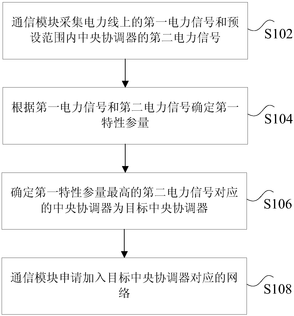
[0032] figure 1 is a flowchart of a method for identifying household-change relationships according to an embodiment of the present invention, such as figure 1 As shown, the method includes the following steps:

[0033] Step S102, the communication module collects the first power signal on the power line and the second power signal of the central coordinator within a preset range.

[0034] Specifically, the above-mentioned communication module may be a STA (station, station), may include...

Embodiment 2

[0086] According to an embodiment of the present invention, a device for identifying a household-change relationship is provided, Figure 5 It is a device for identifying household-change relationships according to an embodiment of the present invention, combined with Figure 5 As shown, the device includes:

[0087] The collection module 50 is used for the communication module to collect the first power signal on the power line and the second power signal of the central coordinator within a preset range.

[0088] The first determination module 52 is configured to determine a first characteristic parameter according to the first power signal and the second power signal.

[0089] The second determination module 54 is configured to determine that the central coordinator corresponding to the second power signal with the highest first characteristic parameter is the target central coordinator.

[0090] The application module 56 is used for the communication module to apply for j...

Embodiment 3

[0092] According to an embodiment of the present invention, a storage medium is provided, which is characterized in that the storage medium includes a stored program, wherein, when the program is running, the device where the storage medium is located is controlled to execute the method for identifying user-change relationships in Embodiment 1.


PUM


Abstract

The invention discloses a user change relationship identifying method and device. The method includes: a communication module collects first power signals on a power line and second power signals of central coordinators within a preset range; first characteristic parameters are determined according to the first power signals and the second power signals; a central coordinator corresponding to thesecond power signal with the highest first characteristic parameter is determined as a target central coordinator; and the communication module applies to join a network corresponding to the target central coordinator. The user change relationship identifying method solves the technical problem that line loss is difficult to accurately calculate due to user change relationship errors in the priorart.

Description

technical field [0001] The present invention relates to the field of electric power communication, in particular, to a method and device for identifying household-to-change relationships. Background technique [0002] The fine-grained management of line loss in low-voltage station area means that the power supply enterprise takes the distribution station area as the unit, applies the power consumption information collection system to realize the real-time statistics of the line loss in the distribution station area, and compares the theoretical line loss calculation data with the actual line loss The comparison and analysis of data can reasonably determine the qualified value of line loss management in the distribution station area, and the reason can be found out in time for the low-voltage station area where the line loss deviates from the target value, so that the line loss rate of the low-voltage station area can be maintained at a normal level for a long time . The err...

Claims


Application Information

Patent Timeline
Patent Type & Authority Applications(China)
IPC IPC(8): G08C19/00G08C25/00H04B3/54
CPCG08C19/00G08C25/00H04B3/54
Inventor 李国昌李冀羡慧竹宋玮琼李蕊李海涛姜洪浪赵成赵磊郭帅刘恒徐德超万剑
Owner STATE GRID BEIJING ELECTRIC POWER
Why Eureka
Try Eureka