Micro actuator
A technology of micro-actuator and driving mechanism, applied in the field of micro-electromechanical, can solve problems such as inability to meet precision control, and achieve the effect of meeting the needs of precise control
- Summary
- Abstract
- Description
- Claims
- Application Information
AI Technical Summary
Problems solved by technology
Method used
Image
Examples
no. 1 example
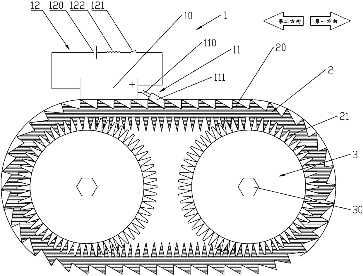
[0029] Please refer to figure 2 , Figure 4 , in an embodiment of the present invention, a micro-driver is provided, a driving principle is provided, and its driving action process is described.
[0030] The micro-driver includes: a driving mechanism 1 , a conducting mechanism 2 and a driven mechanism 3 .
[0031] The driving mechanism 1 includes: a telescopic member 10 made of electrically strained material, a propulsion assembly 11, and a control circuit 12, specifically, the telescopic member 10 is piezoelectric ceramics, and the propulsion assembly 11 includes: a limit rod 110 and a push piece 111 , the control circuit 12 includes: a constant current power supply 120 , an inductive switch 121 and an inductor 122 . One end of the piezoelectric ceramic is fixed, and the other end of the piezoelectric ceramic is fixed with a limit rod 110 , the center of the limit rod 110 is fixed on the other end of the piezoelectric ceramic, and the push piece 111 is installed at both en...
no. 2 example
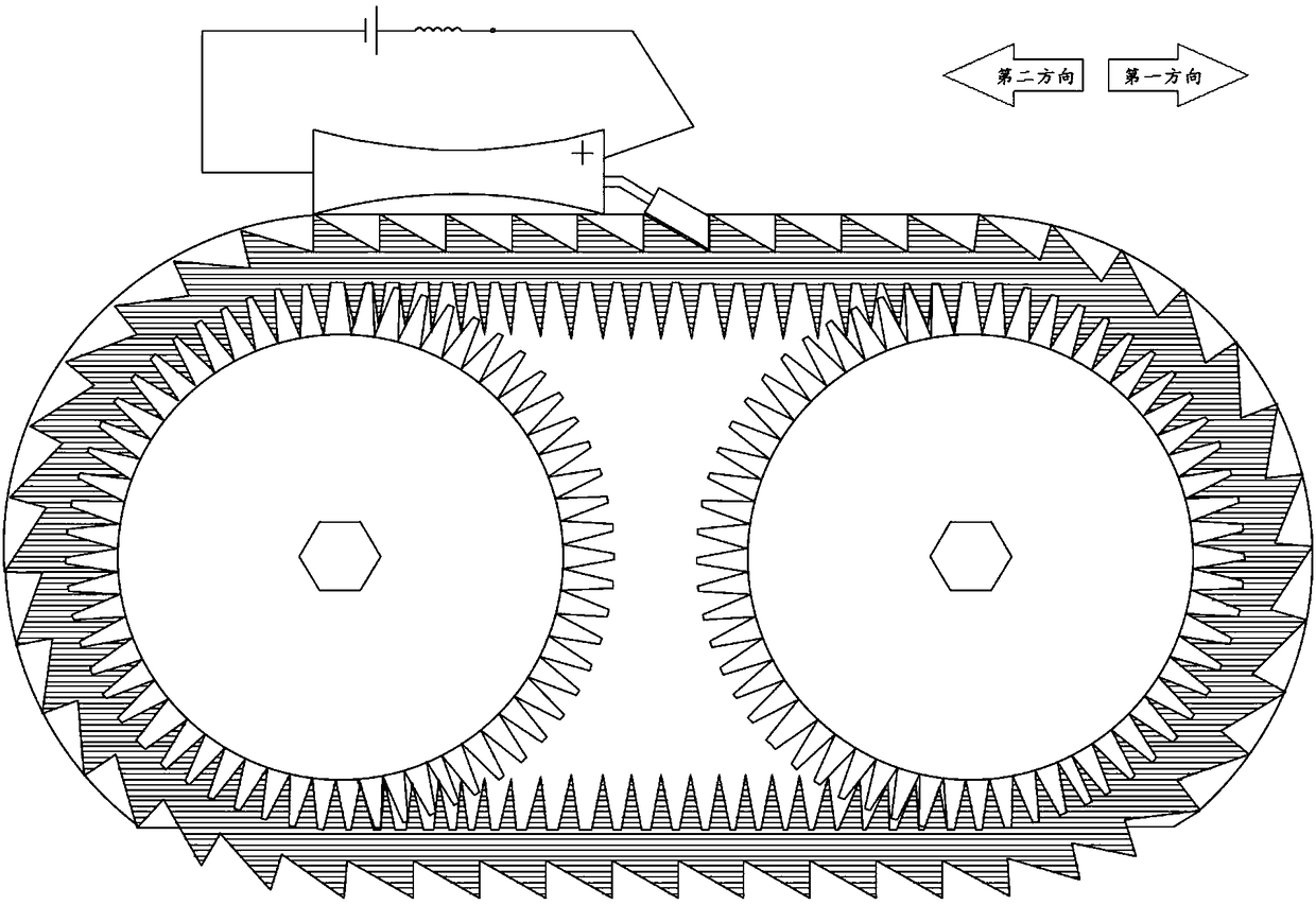
[0039] Please refer to image 3 , Figure 4 In an embodiment of the present invention, a micro-driver using another driving principle is provided, and its driving action process is described.
[0040] The micro-driver includes: a driving mechanism 1 , a conducting mechanism 2 and a driven mechanism 3 .
[0041] The drive mechanism includes: a telescopic member 10 made of electrically strained material, a propulsion assembly 11, and a control circuit 12, specifically, the telescopic member 10 is piezoelectric ceramics, and the propulsion assembly 11 includes: a limit rod 110 and a push piece 111, The control circuit 12 includes: a constant current power supply 120 , an inductive switch 121 and an inductor 122 . One end of the piezoelectric ceramic is fixed, and the other end of the piezoelectric ceramic is fixed with a limit rod 110, the center of the limit rod 110 is fixed on the other end of the piezoelectric ceramic, and the push piece 111 is installed at both ends of the ...
no. 3 example
[0048] The wheel belt provided by the present invention uses 36 tooth grooves.
[0049] Please refer to figure 2 , Figure 4 and Figure 6 , Figure 6 In order to use the wheeled micro-robot driven by the micro-driver provided by the present invention, the power is output by inserting the rotating shaft 40 and the rotating wheel 41 in the power output hole 30 at the center of the tire belt. The radius of the rotating wheel 41 is r, and the radius of the rotating wheel 41 is r. The circumference is 2πr (μm). If the action scale of the piezoelectric ceramic is 5 μm, it means that the piezoelectric ceramic pushes the wheel belt to travel a distance of 1 slot width each time, which means that the wheel belt drives the driven wheel to rotate 1 / 36×360 °=10° angle, because the rotating wheel 41 is coaxial with the driven wheel, then the rotating wheel 41 also rotates at the same angle, which means that the rotating distance of the rotating wheel 41 is 10 / 360×2πr=πr / 18 (μm), then ...
PUM
 Abstract
Description
Claims
Application Information
 - R&D
- Intellectual Property
- Life Sciences
- Materials
- Tech Scout
- Unparalleled Data Quality
- Higher Quality Content
- 60% Fewer Hallucinations
Browse by: Latest US Patents, China's latest patents, Technical Efficacy Thesaurus, Application Domain, Technology Topic, Popular Technical Reports.
© 2025 PatSnap. All rights reserved.Legal|Privacy policy|Modern Slavery Act Transparency Statement|Sitemap|About US| Contact US: help@patsnap.com


