
Calibration device and method for a laser cloud particle imager

A technology of laser cloud particles and calibration method, which is applied to measurement devices, instruments, scientific instruments, etc., can solve the problems of inability to measure the depth of field of cloud particle imaging and lack of accurate scale, and achieve the effect of simple structure, high precision and easy realization.

Active Publication Date: 2021-10-29
北京中兵人影科技有限公司
View PDF7 Cites 0 Cited by
  • Summary
  • Abstract
  • Description
  • Claims
  • Application Information

AI Technical Summary

Problems solved by technology

The speed of the motor of this device is fixed, and the linear speed of the black dot is much lower than the actual working airspeed of the CIP. It can only be adjusted manually in a small range, and there is no precise scale, so it is impossible to measure the imaging depth of cloud particles of various sizes.

Method used


Image

  • Calibration device and method for a laser cloud particle imager
  • Calibration device and method for a laser cloud particle imager
  • Calibration device and method for a laser cloud particle imager

Examples


Embodiment 1

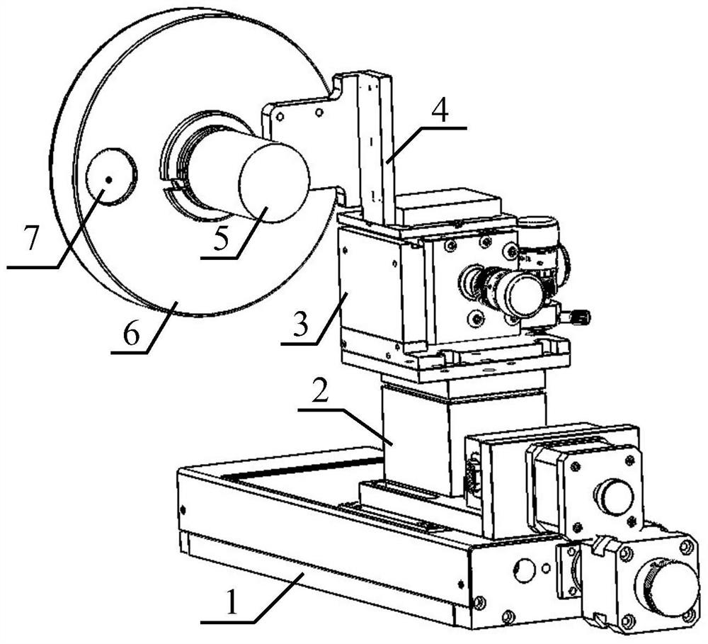
[0050] Example 1, such as figure 1 As shown, a calibration device of a laser cloud particle imager according to an embodiment of the present invention includes: an electric translation stage 1, an electric lift stage 2, a multi-axis displacement stage 3, a DC motor 5, a glass-carrying disc 6 and three Calibration glass beads7.

[0051] The electric translation platform 1 is placed horizontally and the table top is parallel to the ground. The electric lifting platform 2 is vertically placed on the electric translation platform 1, and the bottom surface is fixed on the table top of the electric translation platform 1. The multi-axis displacement platform 3 is vertically placed on the electric lifting platform 2, and the bottom surface is fixed on the table surface of the electric lifting platform 2. The DC motor 5 is fixed on the table top of the multi-axis translation stage 3 through the adapter plate 4 . The glass-carrying disc 6 is fixedly connected with the rotating shaft...

Embodiment 2

[0057] Embodiment 2, a calibration method of a calibration device of a laser cloud particle imager, which is used to calibrate the median comparison voltage of the laser cloud particle imager, the magnification of the imaging optical system, and the imaging depth of field for measuring particles of different sizes. The calibration method Include the following steps:

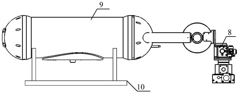
[0058] Step 1, place the laser cloud particle imager 9 horizontally on the support frame 10, and ensure that the light beam emitted by the laser cloud particle imager 9 can be kept horizontal along the X-axis direction.


PUM


Abstract

The invention discloses a calibration device for a laser cloud particle imager, which includes an electric translation platform, an electric lifting platform, a multi-axis displacement platform, a DC motor, a glass-carrying disc and calibration glass beads, the table top of the electric translation platform and the electric lifting platform. The bottom surface of the stage is fixedly connected, the tabletop of the electric lift table is fixedly connected with the bottom surface of the multi-axis translation stage, the tabletop of the multi-axis translation stage is fixedly connected with the DC motor through the adapter plate, and the shaft of the DC motor is fixedly connected with the glass-carrying disk, and the calibration glass The beads are bonded to the glass-carrying disc, and the motorized translation stage, motorized lift table and DC motor are connected to the computer through cables. The invention also discloses a calibration method of the laser cloud particle imager. The present invention utilizes calibration glass beads of standard size to simulate cloud particles as realistically as possible, cooperates with a multi-dimensional combined translation platform to precisely adjust the median comparison voltage of the calibrated laser cloud particle imager and the magnification of the imaging optical system to measure the particle size of various particles. True imaging depth of field.

Description

technical field [0001] The invention relates to the technical field of meteorological airborne detection, in particular to a calibration device and method for a laser cloud particle imager. Background technique [0002] The laser cloud particle imager can be used to directly image cloud droplet particles, and can measure the corresponding particle size spectrum, calculate water content and number concentration and other parameters, and its measurement data is of great importance for studying the physical process of cloud precipitation and guiding weather modification operations effect. The laser cloud particle imager uses a red semiconductor laser as the light source, and a 64-element one-dimensional linear array photodetector to receive the signal. During the measurement, the laser cloud particle imager is fixed under the wing of the aircraft. When the aircraft flies in the cloud, the cloud droplet particles fly along the direction perpendicular to the optical path relativ...

Claims


Application Information

Patent Timeline
Patent Type & Authority Patents(China)
IPC IPC(8): G01W1/02G01S7/497G01S17/95G01S17/89
CPCG01S7/497G01S17/89G01S17/95G01W1/02Y02A90/10
Inventor 郭学良伍波王乐于子平杨泽厚孙海铎
Owner 北京中兵人影科技有限公司
Learn More