Conveying mechanism of plate cutting device

A technology of cutting device and conveying mechanism, which is applied in the field of machinery, can solve problems such as low production efficiency, and achieve the effects of improving production efficiency, cutting quality and production speed

Inactive Publication Date: 2018-07-27
海宁市纵达新材料股份有限公司
View PDF4 Cites 3 Cited by
  • Summary
  • Abstract
  • Description
  • Claims
  • Application Information

AI Technical Summary

Problems solved by technology

This kind of plate cutting equipment needs to stay during cutting, resulting in low production efficiency

Method used


Image

  • Conveying mechanism of plate cutting device
  • Conveying mechanism of plate cutting device
  • Conveying mechanism of plate cutting device

Examples


Embodiment Construction

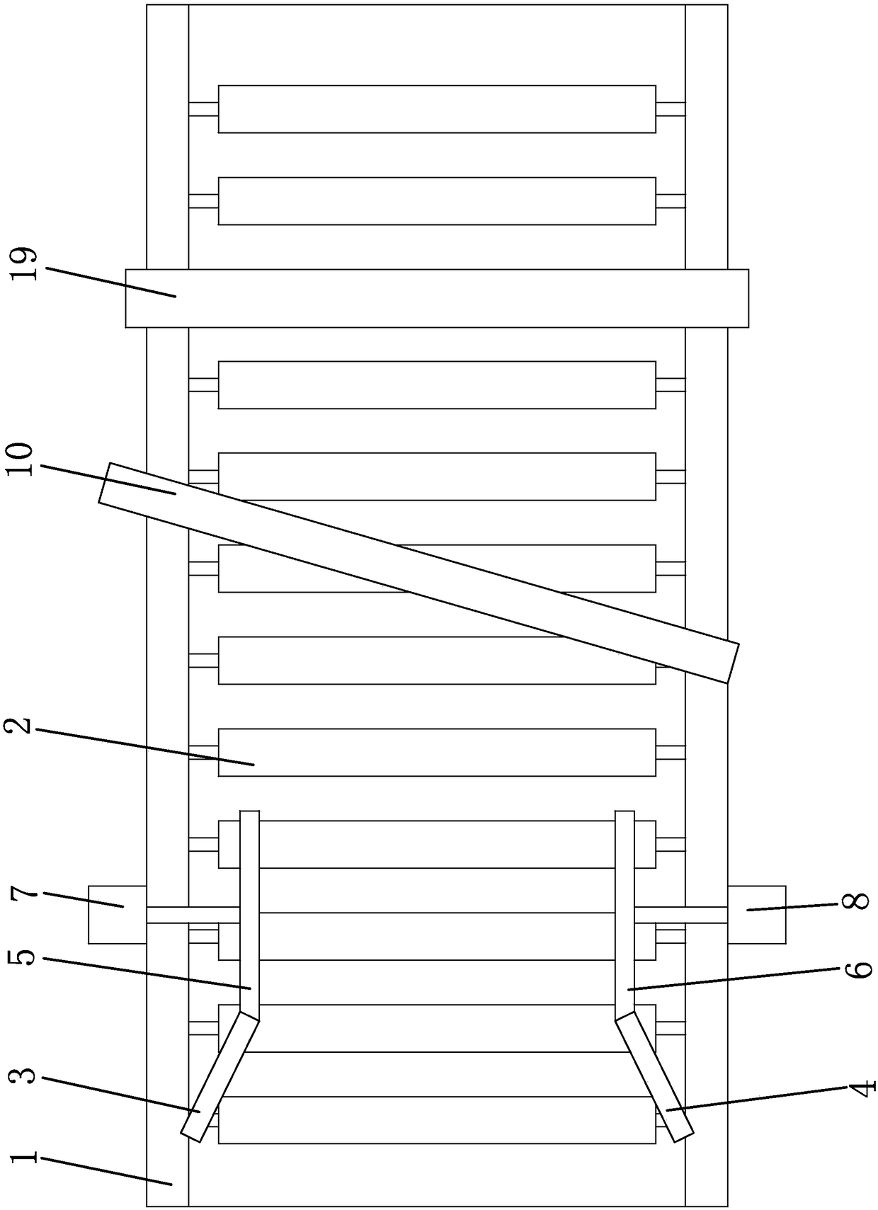
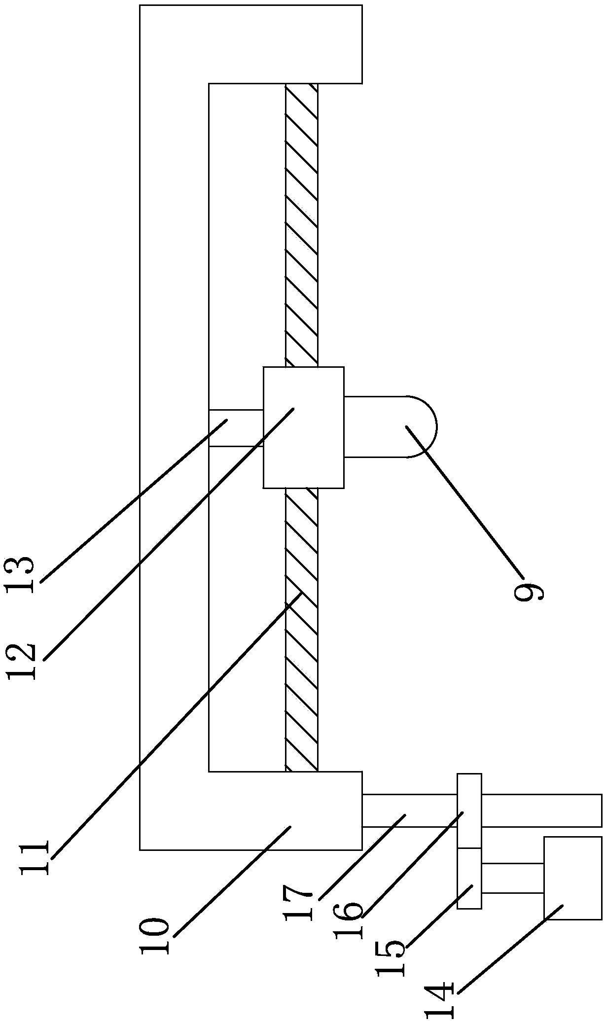
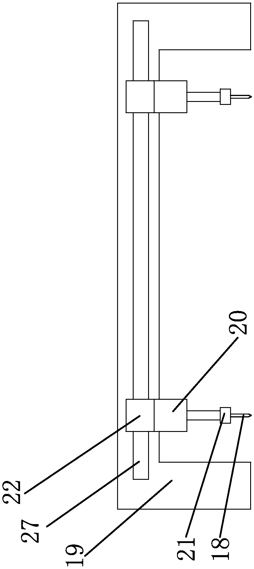
[0027] The following are specific embodiments of the present invention and in conjunction with the accompanying drawings, the technical solutions of the present invention are further described, but the present invention is not limited to these embodiments.

[0028] like figure 1 , figure 2 , image 3 , Figure 4 As shown, a conveying mechanism of a plate cutting device, the plate cutting device includes a strip-shaped workbench 1, the workbench 1 has an input end and an output end, the conveying mechanism includes a number of conveying rollers 2, and the conveying rollers 2 rotate in the circumferential direction And the way of axial fixing is set on the workbench 1, one end of the conveying roller 2 is fixed with a gear one, and the other end of the conveying roller 2 is fixed with a bearing one, several gears are connected by a chain one, and one end of the chain one is also meshed One gear and two, a drive motor is fixed on one side of the workbench 1, and the output sh...


PUM


Abstract

The invention provides a conveying mechanism of a plate cutting device, and belongs to the technical field of machinery. The conveying mechanism solves the problem of low conveying efficiency in the prior art. The conveying mechanism of the plate cutting device is characterized in that the plate cutting device comprises a long strip-shaped work table; the work table is provided with an input end and an output end; the conveying mechanism comprises a plurality of conveying rollers; the conveying rollers are arranged on the work table in a peripheral rotation and axial fixed mode; one end of theconveying roller is fixedly provided with a first gear; the other end of the conveying roller is fixedly provided with a first bearing; a plurality of first gears are connected through a first chain;one end of the first chain is also engaged with a second gear; a driving motor is fixed onto one side of the work table; an output shaft of the driving motor is fixedly provided with the second gear.The conveying mechanism has the advantage that the conveying efficiency is high.

Description

technical field [0001] The invention belongs to the technical field of machinery, and relates to a cutting device, in particular to a conveying mechanism of a plate cutting device. Background technique [0002] After searching, for example, the Chinese patent literature discloses a plate cutting equipment [Application No.: 201610214364.9]; this plate cutting equipment includes a basic support, a cutting platform, a feeding platform, a discharging platform, a cutting machine mounting Cutting machine; wherein, the cutting platform, the feeding platform, the discharging platform and the cutting machine installation frame are all fixed to the basic support; the top of the basic support is discretely distributed with a plurality of downward telescopic Cylinder; the cutting bench is discretely distributed with a plurality of upward telescopic cylinders; the upward telescopic cylinders correspond to the downward telescopic cylinders one by one, and are used to clamp the top surface...

Claims


Application Information

Patent Timeline
Patent Type & Authority Applications(China)
IPC IPC(8): B27C5/02B27C5/04B27C5/06B27M1/08
CPCB27C5/02B27C5/04B27C5/06B27M1/08
Inventor 周明英
Owner 海宁市纵达新材料股份有限公司
Why Eureka
Try Eureka