Printing device and conveying device

A technology for printing devices and conveying devices, applied in printing devices, printing, typewriters, etc., can solve the problems of reduced suction force of media, achieve the effect of ensuring suction force and expanding the suction range

Active Publication Date: 2021-04-13
SEIKO EPSON CORP
View PDF1 Cites 0 Cited by
  • Summary
  • Abstract
  • Description
  • Claims
  • Application Information

AI Technical Summary

Problems solved by technology

Therefore, the suction force acts as a force to suck in the outside air, resulting in a decrease in the suction force for the medium

Method used


Image

  • Printing device and conveying device
  • Printing device and conveying device
  • Printing device and conveying device

Examples


no. 1 approach

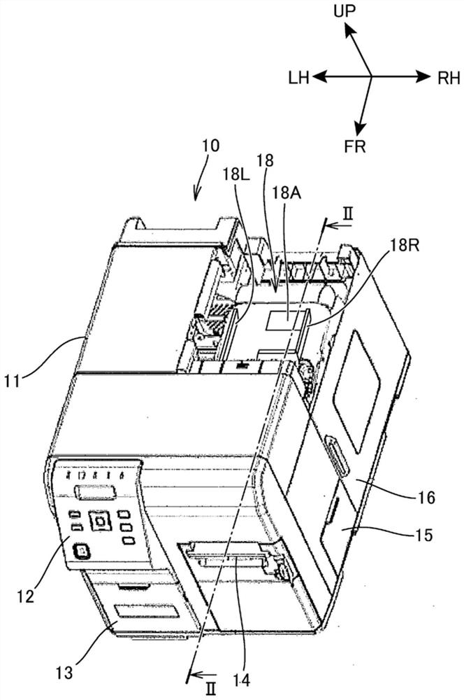
[0034] figure 1 It is a diagram showing the appearance of the printing device 10 according to the first embodiment of the present invention.

[0035] The printing device 10 is a printer that prints on continuous paper S (recording medium, medium) such as label paper formed by attaching labels to elongated backing paper at constant intervals, and is also called a label printer. The printing device 10 is wired or wirelessly connected to an information processing terminal via a USB (Universal Serial Bus) cable or a LAN (Local Area Network) Print data to implement printing.

[0036] exist figure 1 In each figure described later, the symbol FR represents the front of the printing device 10 , the symbol LH represents the left side of the printing device 10 , the symbol RH represents the right side of the printing device 10 , and the symbol UP represents the upper side of the printing device 10 .

[0037] Such as figure 1 As shown, the printing device 10 has a rectangular paralle...

no. 2 approach

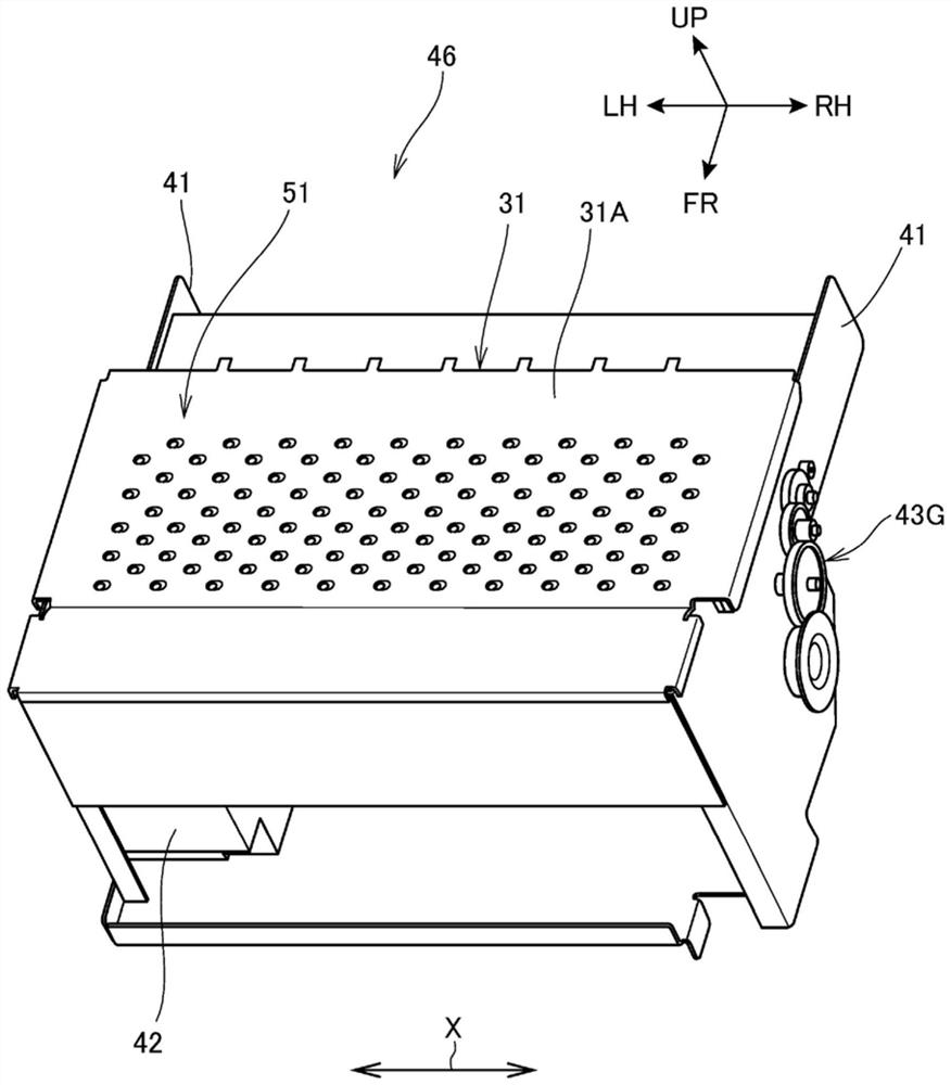
[0119] The printing apparatus 10 according to the second embodiment differs from the printing apparatus 10 in that it includes a guide unit 18 for conveying the continuous paper S at the center and in a part of the suction holes 51 that suck the platen 31 . The first embodiment is the same. In addition, the guide unit 18 which is placed in the center and carries out conveyance only needs to apply a well-known guide unit, and the description is abbreviate|omitted.

[0120] Figure 12 It is a figure which looked at the suction platen 31 of the printing apparatus 10 which concerns on 2nd Embodiment from above. Since the guide unit 18 centers and conveys the continuous paper S, the center LC of the continuous paper S on the suction platen 31 is always the same.

[0121] Such as Figure 12 As shown, the suction platen 31 is provided with a first suction hole 51A and a second suction hole 51B as a plurality of suction holes 51, wherein the first suction hole 51A is provided on th...


PUM


Abstract

The present invention provides a printing device and a conveying device capable of efficiently expanding the suction range of a suction hole and ensuring a suction force for a medium even if a gap is formed between the end of the medium and the suction hole , and can suppress the influence on the ink droplet. Wherein, the suction hole provided on the suction platen is formed into a shape including a second opening (minimum opening) in a width direction intersecting with a conveying direction of the continuous paper (medium). The length is shorter than the length of the suction hole on the mounting surface. In addition, it is formed so that the center position of the suction hole in the width direction in the second opening is located on one side in the width direction than the center position of the suction hole in the width direction on the mounting surface.

Description

technical field [0001] The invention relates to a printing device and a conveying device. Background technique [0002] A printing device is known which has an inkjet head which ejects ink onto the conveyed medium and a suction platen (also called suction plate) which has a A loading surface on which the medium is loaded and a suction hole opened on the loading surface. [0003] Such a printing device discloses a structure in which the suction area is increased by making the suction holes expand toward the mounting surface (for example, refer to Patent Document 1). In addition, Patent Document 1 also describes that the pressure distribution in the suction hole is made uniform by making the suction hole expand toward the mounting surface in a funnel shape, and the formation of suction is improved. Operability during hole. [0004] However, in the conventional structure, if there is a gap between the end of the medium and the suction hole, the gap and the smallest opening o...

Claims


Application Information

Patent Timeline
Patent Type & Authority Patents(China)
IPC IPC(8): B41J2/01B41J11/00
CPCB41J2/01B41J11/0085B41J3/4075B41J11/06B41J2/04B41J11/007B41J11/02B41J11/057B41J13/226
Inventor 平嶋拓
Owner SEIKO EPSON CORP
Why Eureka
Try Eureka