Collection box of waste drip bottles for nursing department

A storage box and drip bottle technology, applied in the medical field, can solve the problems of troublesome handling, small storage capacity of cartons, inconvenient handling, etc., and achieve the effects of easy dumping, expansion of storage capacity, and reduction of breakage.

Inactive Publication Date: 2018-07-27
吕东霞
6 Cites 1 Cited by

AI-Extracted Technical Summary

Problems solved by technology

[0003] Nursing departments of existing hospitals discard a lot of drip bottles, drip bags and infusion bags every day. These drip bottles, drip bags and infusion bags are often put into cartons for collection. Sometimes the cartons will be full in less than a day. Small, inconvenient to car...

Method used

Concrete, the discharge opening place of described second feeding port 25 and be positioned at the inside of glass drop bottle storage box 12 are provided with material guide plate, the bottom of described material guide plate and be positioned at glass drop bottle storage box 12 The left side wall of the tank is provided with a stepped buffer plate, and the surface of the buffer plate is bonded with a rubber pad to reduce the breakage of the glass drip bottle, and avoid the broken glass on the glass drip bottle brought by the transfer process in the future from scratching the transfer personnel.
This nursing department discards storage box with drop bottle, the drop bottle of plastic product and the drop bottle classification of glass product are processed, when processing the drop bottle of plastic product, the drop bottle of plastic product is placed in placement groove 16, by Slider 21 moves down, punctures the plastic drip bottle with piercing needle 22, and then pushes the pressing block 24 through th...

Abstract

The invention discloses a collection box of waste drip bottles for a nursing department. The collection box comprises a mounting base and a collection box unit, wherein hydraulic cylinders are fixedlyarranged on the left and right sides of the top of the mounting base; the end parts of hydraulic rods on the hydraulic cylinders are hinged to the bottom of the collection box unit through hinge parts; one active wheel group and two passive wheel groups are arranged at the bottom of the mounting base; the collection box unit comprises a plastic drip bottle collection box and a glass drip bottle collection box; a first feed inlet is formed in the plastic drip bottle collection box; a flattening device of the drip bottles is arranged in the position, on the left side of the first feed inlet, ofthe top of the collection box unit; pressing blocks are fixedly connected to the end parts of telescopic rods of cylinders; and a second feed inlet is formed in the top of the glass drip bottle collection box. After the collection box of the waste drip bottles for the nursing department is filled with the drip bottles, the collection box is conveniently moved, the drip bottles are conveniently unloaded, the glass and plastic drip bottles are separately collected, and the plastic drip bottles are compressed to be collected.

Application Domain

Technology Topic

Image

  • Collection box of waste drip bottles for nursing department
  • Collection box of waste drip bottles for nursing department
  • Collection box of waste drip bottles for nursing department

Examples

  • Experimental program(1)

Example Embodiment

[0022] The technical solutions in the embodiments of the present invention will be clearly and completely described below with reference to the accompanying drawings in the embodiments of the present invention. Obviously, the described embodiments are only a part of the embodiments of the present invention, but not all of the embodiments. Based on the embodiments of the present invention, all other embodiments obtained by those of ordinary skill in the art without creative efforts shall fall within the protection scope of the present invention.
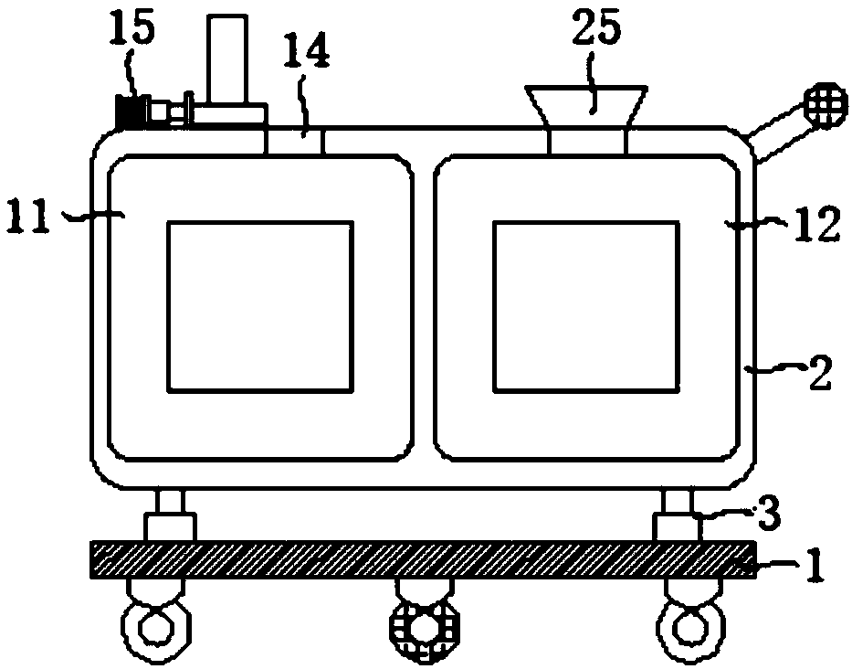
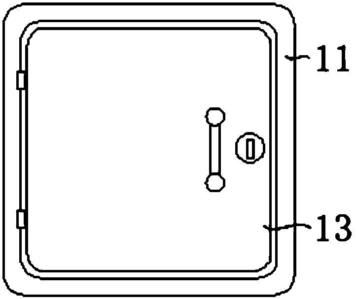
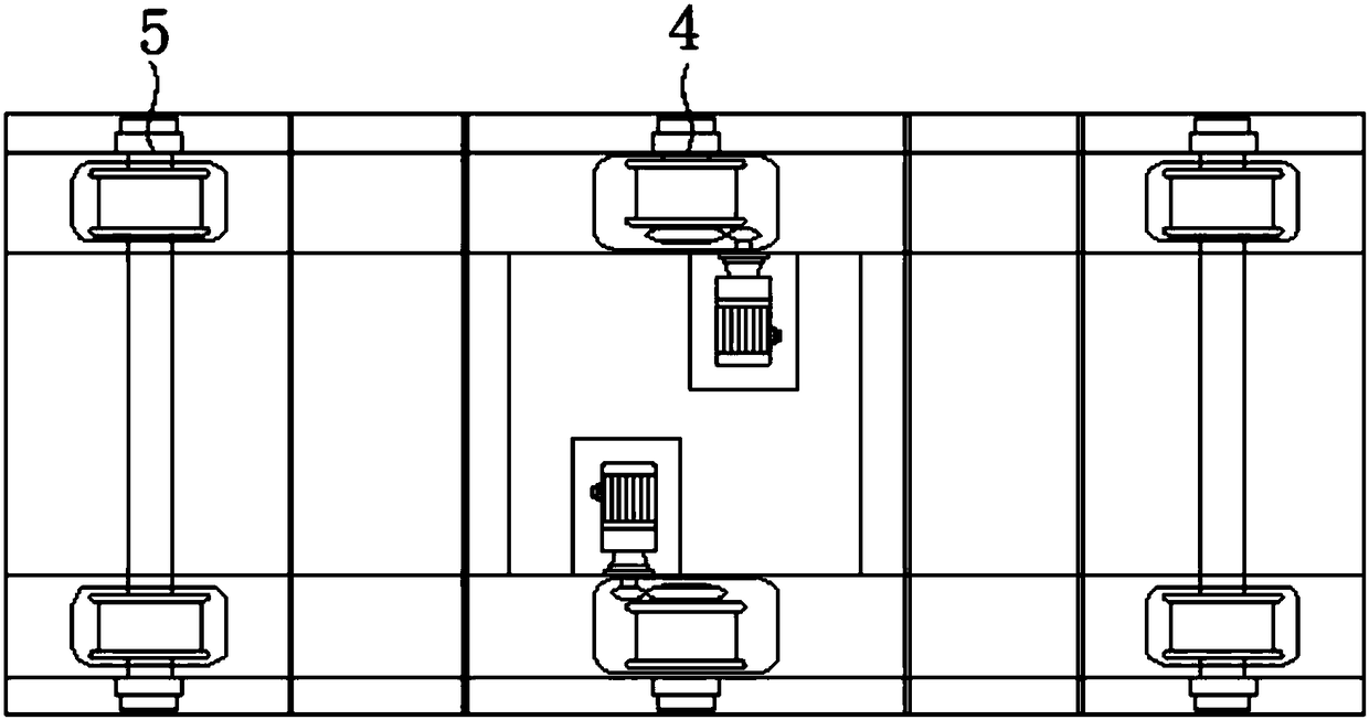
[0023] The present invention provides such as Figure 1-6 Shown is a discarded storage box for drip bottles for nursing, including a mounting seat 1 and a storage box 2, and a hydraulic cylinder 3 is fixed on the left and right sides of the top of the mounting seat 1, and the end of the hydraulic rod on the hydraulic cylinder 3 is fixed. The part is hingedly connected to the bottom of the storage box 2 through a hinge, the bottom of the mounting seat 1 is provided with a group of active wheel assemblies 4 and two groups of passive wheel groups 5, and the two groups of the passive wheel groups 5 are located at the bottom of the mounting seat 1 on the left and right sides. On the other hand, a group of said driving wheel assemblies 4 includes an electric motor 6 and a reducer 7, the output shaft of the electric motor 6 is drivingly connected with the input shaft of the reducer 7 through a coupling, and the end of the output shaft of the reducer 7 The pinion gear 8 is meshed with the large gear 10 on the drive shaft of the driving wheel 9. The storage box 2 includes a plastic drip bottle storage box 11 and a glass drip bottle storage box 12. The plastic drip bottle storage box 11 is provided with a first feed. Port 14, on the left side of the first feeding port 14 and at the top of the storage box 2 is a squashing device 15 for drip bottles, the squashing device 15 includes a placement slot 16, and the left side of the placement slot 16 is provided. An electric push rod 17 is provided, the end of the telescopic rod of the electric push rod 17 is connected with a push plate 18, and the vertical plate 19 on the rear side of the placement slot 16 is provided with a chute 20, and the chute 20 is slidably connected There is a sliding block 21, the bottom of the sliding block 21 is connected with a puncture needle 22 through a connecting block, and two cylinders 23 are provided on the left and right sides of the top of the sliding block 21, and the ends of the telescopic rods of the cylinder 23 are fixedly connected with The pressing block 24, the top of the glass drip bottle storage box 12 is provided with a second feeding port 25.
[0024] Specifically, both the left side of the plastic drip bottle storage box 11 and the right side of the glass drip bottle storage box 12 are hinged with a box side cover 13 through hinges.
[0025] Specifically, the box side cover 13 is provided with a mechanical lock matching the storage box 2 , and the box side cover 13 is provided with a door handle.
[0026] Specifically, the front side of the plastic drip bottle storage box 11 and the glass drip bottle storage box 12 is provided with a see-through window.
[0027] Specifically, a hand push rod is provided on one side of the storage box 2 .
[0028] Specifically, the sliding block 21 is a horizontal T-shaped sliding block, and the bottom of the sliding block 21 is fixedly provided with a pushing mechanism that drives the sliding block to move up and down.
[0029] Specifically, the pressing block 24 is provided with a through hole matching with the puncturing needle 22 , and the pressing block 24 is also provided with a ventilation hole.
[0030] Specifically, a material guide plate is provided at the discharge port of the second feeding port 25 and located inside the glass drip bottle storage box 12 , and the bottom of the material guide plate is located on the left side of the glass drip bottle storage box 12 . The wall is provided with a stepped buffer plate, and the surface of the buffer plate is bonded with a rubber pad to reduce the breakage of the glass drip bottle and avoid the broken glass on the glass drip bottle brought by the future transfer process from scratching the transfer personnel.
[0031] The nursing department uses the discarded drip bottle storage box to classify the plastic drip bottle and the glass drip bottle. When handling the plastic drip bottle, place the plastic drip bottle in the placing slot 16 and pass the slider 21 move down, use the puncture needle 22 to pierce the plastic drip bottle, then push the pressure block 24 through the cylinder 23 to drain the air in the plastic drip bottle, flatten the plastic drip bottle, and finally use the electric push rod 17 to drive the push plate 18 Push the flattened plastic drip bottle into the plastic drip bottle storage box 11, which can expand the storage capacity of the plastic drip bottle storage box 11 for the drip bottle. When processing the glass product drip bottle, the glass is directly injected through the second feeding port 25. It can be placed in the drip bottle storage box 12. The design of the guide plate and the buffer plate in the glass drip bottle storage box 12 is to reduce the breakage of the glass drip bottle and avoid the broken glass on the glass drip bottle caused by the transfer process in the future. In addition, an active wheel assembly 4 and a passive wheel set 5 are designed on the mounting base 1 to facilitate the transfer of IV bottles, IV bags and infusion bags in the future, and the side cover 13 and hydraulic cylinder 3 of the box are designed to facilitate the storage box 2 dumping of waste.
[0032] Finally, it should be noted that the above descriptions are only preferred embodiments of the present invention, and are not intended to limit the present invention. Although the present invention has been described in detail with reference to the foregoing embodiments, for those skilled in the art, the The technical solutions described in the foregoing embodiments can be modified, or some technical features thereof can be equivalently replaced, and any modifications, equivalent replacements, improvements, etc. made within the spirit and principle of the present invention shall be included. within the protection scope of the present invention.

PUM

no PUM

Description & Claims & Application Information

We can also present the details of the Description, Claims and Application information to help users get a comprehensive understanding of the technical details of the patent, such as background art, summary of invention, brief description of drawings, description of embodiments, and other original content. On the other hand, users can also determine the specific scope of protection of the technology through the list of claims; as well as understand the changes in the life cycle of the technology with the presentation of the patent timeline. Login to view more.

Similar technology patents

Drill Cuttings Methods and Systems

ActiveUS20120181086A1Increase storage capacityMaximize available spaceLarge containersFlushingDrill cuttingsEngineering
Owner:KMC OIL TOOLS

Classification and recommendation of technical efficacy words

  • Increase storage capacity
  • Reduce broken

Display apparatus

Owner:INTELLECTUAL KEYSTONE TECH

Method for expanding tobacco shred

ActiveCN101513272AGood swelling effectReduce brokenTobacco preparationWater contentChemistry
Owner:YUNNAN REASCEND TOBACCO TECH GRP +1

Novel low-density tobacco packet remoistening device

ActiveCN102188038AReduce brokenSave steamTobacco preparationGeometric formWetting
Owner:QINHUANGDAO TOBACCO MACHINERY

Device and technology for loosening treatment on tobacco sheet bag

InactiveCN102920017AImprove loose efficiencyReduce brokenCigarette manufactureLoading/unloadingEngineeringTobacco leaf
Owner:YUNNAN KUNMING SHIPBUILDING DESIGN & RESEARCH INSTITUTE

Method for keeping regenerator temperature stable in low carbon alkene preparation

ActiveCN101328102AAlleviate cold collapseReduce brokenHydrocarbon from oxygen organic compoundsChemical recyclingOxygen compoundMolecular sieve
Owner:CHINA PETROLEUM & CHEM CORP +1

People also interested in

Why Eureka
Try Eureka