Generator rotor automatic feeding mechanism

A generator rotor and automatic feeding technology, which is applied in the direction of conveyors, conveyor objects, transportation and packaging, etc., can solve the problem of low automation and achieve the effect of a reasonable and compact structure of the positioning mechanism

Pending Publication Date: 2018-07-27
JULI AUTOMATION EQUIP ZHEJIANG CO LTD
0 Cites 0 Cited by

AI-Extracted Technical Summary

Problems solved by technology

In the conveying device of the existing generator rotor automatic feeding machine, the deg...

Method used

Rotor 8 lateral movement devices are connected with frame 1 by support frame 5, and the purpose of rotor 8 lateral movement devices is to move the row of rotors 8 that are positioned at the front end to the rotor 8 positioning mechanism 9 that is fixed on frame 1 side , move the rotor 8 closest to the positioning mechanism 9 to the positioning mechanism 9, which is not shown in the figure. The rotor 8 lateral movement device comprises a first motor 51 at one end of the support frame 5 and a sliding device 52. The first motor 51 drives the sliding device 52 to move along the support frame 5 through a screw mandrel. The screw drive is used as a conventional technology in this embodiment. The figures do not show it. The sliding device 52 is connected with the supporting frame 5 through a tank belt 53 . The trachea and lead that are connected with slide device 52 can be put into the tank band 53, and during the movement, tank band 53 moves together with slide device 52, plays protection and the trachea that is connected with slide device 52 and lead.
[0032] The rotor supporting device 3 includes two parallel support rods 31, the length of the support rods 31 matches the width of the frame 1, and there is a set width between the two support rods 31. Two support blocks 32 are arranged equidistantly and fixedly on the support bar 31 , the support blocks 32 are T-shaped as a whole, one end of the support bar 31 is fixed, and the other end is provided with a roller 33 . Slide rails 34 are provided on the frame 1 corresponding to the rollers 33 , so that the rollers 33 can move in the slide rails 34 during the forward...

Abstract

The invention discloses a generator rotor automatic feeding mechanism comprising a conveying mechanism and a positioning mechanism. The conveying mechanism comprises a rotor longitudinal moving deviceand a rotor transverse moving device. The positioning mechanism comprises a positioning plate and a second air cylinder; the positioning plate is fixed to a second fixed plate and composed of a positioning plate base plate and two positioning support plates symmetrically arranged; the positioning support plates are each provided with an inclined end at the set angle; and the second air cylinder can drive a magnet connected with the second air cylinder to move, and the magnet penetrates through the second fixed plate and the positioning plate base plate. The generator rotor automatic feeding mechanism is provided with the conveying mechanism and the positioning mechanism, a rotor longitudinal conveying device and a rotor transverse conveying mechanism are arranged in the conveying mechanism, and thus rotors can be automatically conveyed; and the rotors can be precisely positioned in the positioning mechanism, the rotors can be moved through the magnet connected with the air cylinder, and thus the whole positioning mechanism is more reasonable and more compact in structure.

Application Domain

ConveyorsConveyor parts

Technology Topic

Electric generatorMagnet +1

Image

  • Generator rotor automatic feeding mechanism
  • Generator rotor automatic feeding mechanism
  • Generator rotor automatic feeding mechanism

Examples

  • Experimental program(1)

Example Embodiment

[0028] Example
[0029] Combine Figure 1 to Figure 6 , This embodiment will be described in detail. The automatic feeding mechanism of the generator rotor 8 involved in this embodiment includes a conveying mechanism and a positioning mechanism 9.
[0030] The longitudinal movement device of the rotor 8 includes a chain 2 fixed on the frame 1 and several rotor support devices 3 fixedly connected to the chain 2. The number of chains 2 is two, which are located on both sides of the frame 1, respectively, with a sprocket 4 connected at both ends. The second motor 7 drives the chain 2 through the sprocket 4 at one end, and the sprocket 4 at the other end is driven.
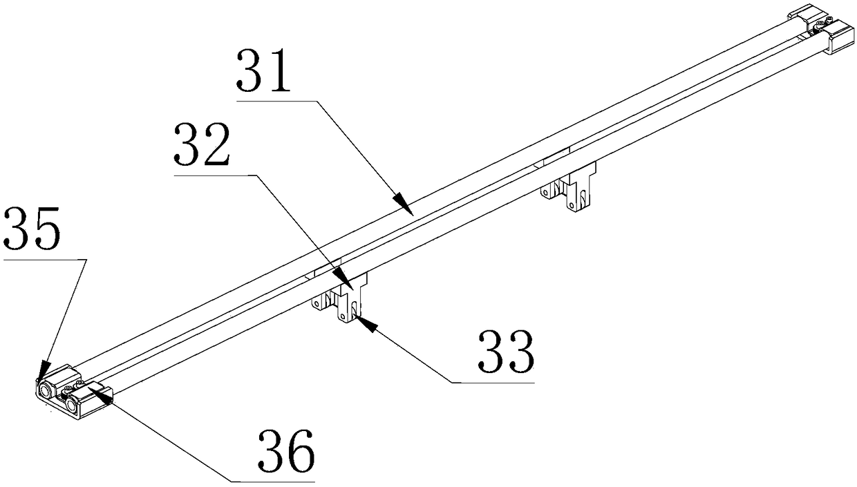
[0031] One chain 2 is fixed to one end of the rotor support device 3, and the other chain 2 is fixed to the other end of the rotor support device 3. The fixing is fixed by a U-shaped plate 35, a folded plate 36 and two bolts. The folded plate 36 and the U-shaped plate 35 form a cavity in which the support rod 31 can be fixed.
[0032] The rotor support device 3 includes two support rods 31 arranged in parallel, the length of the support rod 31 matches the width of the frame 1, and the two support rods 31 have a set width between them. Two supporting blocks 32 are fixedly arranged on the supporting rod 31 at an equal distance. The supporting blocks 32 are T-shaped as a whole, and one end of the supporting rod 31 is fixed, and the other end is provided with a roller 33. The rack 1 is provided with a sliding rail 34 at a position corresponding to the roller 33, so that the roller 33 can move in the sliding rail 34 during the forward movement of the rotor support device 3. When several rotors 8 are located on the rotor support device 3, the support rod 31 may be bent due to the weight of the rotor 8. The function of the support block 32 is to support the support rod 31 so that the support rod 31 will not be The rotor 8 is bent. The arrangement of the roller 33 can make the support rod 31 easier to move forward.
[0033] The rotor 8 lateral movement device is connected to the frame 1 through the support frame 5. The purpose of the rotor 8 lateral movement device is to move the row of rotors 8 at the front end to the positioning mechanism 9 of the rotor 8 fixed on the side of the frame 1. The rotor 8 closest to the positioning mechanism 9 moves to the positioning mechanism 9, which is not shown in the figure. The lateral movement device of the rotor 8 includes a first motor 51 at one end of the support frame 5 and a sliding device 52. The first motor 51 drives the sliding device 52 to move along the support frame 5 through a screw rod. The screw rod drive is a conventional technology in this embodiment. The drawings are not shown. The sliding device 52 is connected to the support frame 5 through a tank belt 53. The trachea and wires connected to the sliding device 52 can be put into the tank belt 53. During the movement, the tank belt 53 moves with the sliding device 52 to protect the trachea and wires connected to the sliding device 52.
[0034] The sliding device 52 is provided with a first cylinder 54 fixed on the first fixing plate 56. A baffle 55 is fixedly connected to one end of the piston rod 921 of the first cylinder 54, and two fixing blocks 57 are also provided on the first fixing plate 56. The fixed block 57 is provided with a sliding groove matching the cross section of the baffle 55, and the baffle 55 can slide along the sliding groove under the driving of the first air cylinder 54. When the piston rod 921 of the first cylinder 54 drives the baffle 55 to move downward, the baffle 55 is in contact with one side of the rotor 8. When the sliding device 52 is driven by the first motor 51 to move to one side, the baffle 55 can push the rotor 8 toward the positioning mechanism 9. When the rotor 8 is pushed to the positioning mechanism 9, the first cylinder 54 raises the baffle 55, and the first motor 51 drives the sliding device 52 to the other end of the support frame 5.
[0035] An infrared detection device 6 is also provided on the frame 1, and the function of the infrared detection device 6 is to detect whether there is a rotor 8 on the frontmost rotor support device 3. If there is no rotor 8 on the rotor support device 3, the second motor 7 drives the chain 2 to move through the sprocket 4, which can make the rotor support device 3 also move forward. When the infrared detection device 6 detects the rotor 8, the second motor The motor 7 stops moving.
[0036] The automatic feeding positioning mechanism 9 for the generator rotor 8 involved in this embodiment includes a positioning plate 91, a second cylinder 92, a magnet 94, and an infrared detection device 6.
[0037] In this embodiment, the positioning plate 91 is fixed on the second fixing plate 93. The positioning plate 91 is composed of a positioning plate base plate 911 and two positioning support plates 912 arranged symmetrically. The positioning support plate 912 has an inclined end inclined outward at a set angle, and the inclined end is connected by a connecting section perpendicular to the positioning plate base plate 911. The angle at which the inclined end of the positioning support plate 912 is inclined, the distance between the vertical connection section of the two positioning support plates 912, and the length of the vertical connection section, combined with the size of the rotor 8, can determine the position of the center position of the rotor 8 and realize the alignment of the rotor. The accurate positioning of 8 lays the foundation for the subsequent processes. A reinforcing plate is provided between the positioning support plate 912 and the positioning plate base plate 911. The strength of the positioning plate 91 can be increased, the impact of the positioning plate 91 due to the impact of the rotor 8 can be reduced, and the service life of the positioning plate 91 can be increased.
[0038] The second cylinder 92 can drive the connected magnet 94 to move. In this embodiment, the second cylinder 92 is connected to the magnet 94 through a piston rod 921 provided thereon. The function of the magnet 94 is to use the magnetic force to move the rotor 8 to the position of the positioning support plate 912 to achieve accurate positioning of the rotor 8. In this embodiment, the rotor 8 has a drum shape in the middle, and rod-shaped protrusions are provided at both ends.
[0039] In this embodiment, the magnet 94 passes through the second fixing plate 93 and the positioning plate substrate 911 is provided with corresponding through holes, and can move in the through holes. The magnet 94 passes through the middle position of the two positioning support plates 912. The second cylinder 92 is fixed on the third fixing plate 95, and the third fixing plate 95 is fixedly connected with the second fixing plate 93 under the fourth fixing plate 96. The fourth fixing plate 96 is perpendicular to the second fixing plate 93, the third fixing plate 95 is perpendicular to the fourth fixing plate 96, and the second fixing plate 93 and the third fixing plate 95 are also in a vertical relationship.
[0040] An infrared detection device 6 is fixedly connected to the second fixing plate 93, and the infrared detection device 6 detects whether there is a rotor 8 on the frontmost rotor support device 3.
[0041] When the rotor 8 is close to the positioning mechanism 9, the second cylinder 92 drives the magnet 94 to extend out of the positioning plate base plate 911 to move the rotor 8 to the position of the positioning support plate 912, see Image 6 To move the rotor 8 to the position of the positioning support plate 912. Due to the inclination angle of the inclined end of the positioning support plate 912, the length and distance of the two vertical connecting sections, the rotor 8 can be positioned to the set position, and the rotor 8 can be accurately positioned. At this time, the clamping mechanism can clamp the rotor 8 to the required position for the next process.
[0042] After a rotor 8 is clamped, whether the infrared detection device 6 has a rotor 8 on the rotor support device 3 at the foremost end of the frame 1, if there is a rotor 8, the first motor 51 drives the sliding device 52 to the frame The left side of 1 moves, and the first baffle 55 is in a raised state at this time to prevent the baffle 55 from contacting the rotor 8. When the sliding device 52 moves to the left side of the frame 1, the first air cylinder 54 lowers the baffle 55, and the first motor 51 drives the sliding device 52 to move to the right. When the baffle 55 is in contact with the rotor 8, it can be moved The rotor 8 is pushed in the direction of the positioning mechanism 9. When the rightmost rotor 8 is close to the positioning mechanism 9, a proximity switch on the positioning mechanism 9 is provided, and the approach of the rotor 8 is detected. At this time, the first motor 51 stops working. An air cylinder 54 raises the baffle 55. The second cylinder 92 of the positioning mechanism 9 extends the magnet 94 toward the rotor 8 through the piston rod 921. After the magnet 94 adsorbs the rotor 8, the second cylinder 92 pulls the rotor 8 toward the positioning support plate 912. 912 accurately positions the rotor 8 so that the clamping mechanism of the rotor 8 clamps the rotor 8 to a position.

PUM

no PUM

Description & Claims & Application Information

We can also present the details of the Description, Claims and Application information to help users get a comprehensive understanding of the technical details of the patent, such as background art, summary of invention, brief description of drawings, description of embodiments, and other original content. On the other hand, users can also determine the specific scope of protection of the technology through the list of claims; as well as understand the changes in the life cycle of the technology with the presentation of the patent timeline. Login to view more.
Why Eureka
Try Eureka