Screeding system using infrared rays and using method thereof

An infrared and rib technology, applied in construction, building structure, etc., can solve problems such as delay time, waste of human resources, line falling and shaking, etc., and achieve the effects of precise construction, convenient operation, and clear and accurate positioning.

Pending Publication Date: 2018-07-27
THE FOURTH OF CHINA CONSTR SEVENTH ENG
View PDF0 Cites 2 Cited by
  • Summary
  • Abstract
  • Description
  • Claims
  • Application Information

AI Technical Summary

Problems solved by technology

[0003] According to conventional methods, during decoration construction, operators often use ordinary hanging hammers and rulers to beat ash cakes first and then punch bars, but this method has many disadvantages: (1) affected by construction technology, people It is often used to beat a certain amount of ash cake with a hammer and a ruler first, and then use a ruler to punch the ribs, which is less effective and the quality control effect is not ideal; (2) some construction sites are too troublesome to directly save the process of punching the ribs, and the quality of the painting is even more difficult Control; (3) Due to the inconvenient suspension of ordinary hanging hammers, it is difficult to hang down from the bottom of th

Method used


Image

  • Screeding system using infrared rays and using method thereof
  • Screeding system using infrared rays and using method thereof
  • Screeding system using infrared rays and using method thereof

Examples


Example Embodiment

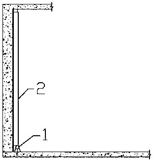
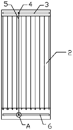
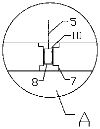
[0029] Example 1: as Figures 1~5 As shown, a rib punching system using infrared rays includes an infrared level 1, a ruler rod 2, and a cutting line 11. The upper end of the ruler rod 2 is provided with an upper chute 3, and an upper slider 4 is movably installed in the upper chute 3. The slider 4 is fixedly connected with one end of the positioning line 5, and the lower part of the ruler rod 3 is provided with a lower sliding groove 6, and a lower sliding block 7 is movably installed in the lower sliding groove 6, and the lower sliding block 7 is provided with a knife groove 10. The cutter 8 is fixedly connected, and the cutter 8 is movably installed in the slot 10 .

Example Embodiment

[0030] Embodiment 2: a kind of punching system using infrared rays, comprising an infrared level 1, a ruler rod 2, a cutting line 11, an upper chute 3 is provided on the upper end of the ruler rod 2, and an upper slider 4 is movably installed in the upper chute 3, The upper slider 4 is fixedly connected with one end of the positioning line 5, the lower part of the ruler rod 3 is provided with a lower slot 6, the lower slider 7 is movably installed in the lower slot 6, the lower slider 7 is provided with a knife slot 10, and the other end of the positioning line 5 It is fixedly connected with the cutter 8, the cutter 8 is provided with a slot I9, the cutter slot 10 is provided with a raised block matched with the slot I9, and the cutter 8 is movably installed in the slot 10.

Example Embodiment

[0031] Embodiment 3: a kind of punching system using infrared rays, comprising an infrared level 1, a ruler rod 2, a cutting line 11, an upper chute 3 is provided on the upper end of the ruler rod 2, and an upper slider 4 is movably installed in the upper chute 3, The positioning line 5 includes two steel wires. One end of the steel wire is fixedly connected with the upper slider 4, and the other end of the steel wire is fixedly connected with the lower slider 7. Two rows of rings are installed on the cutter 8, and the cutter 8 passes through the two lines. The row of circular rings is slidably installed on the two steel wires, and other structures are the same as those in Embodiment 1.


PUM

PropertyMeasurementUnit
Diameteraaaaaaaaaa

Abstract

The invention relates to the field of building decoration construction, in particular to a screeding system using infrared rays and a using method thereof. The components of the system comprise an infrared ray level meter, a ruler rod and a cutting line, wherein an upper sliding groove is formed in the upper end of the ruler rod, an upper sliding block is movably arranged in the upper sliding groove, and the upper sliding block is fixedly connected with one end of a positioning line; a lower sliding groove is formed in the lower part of the ruler rod, a lower sliding block is movably arrangedin the lower sliding groove, the lower sliding block is provided with a cutter groove, a cutter is fixedly connected with the other end of the positioning line, and the cutter is movably arranged in the cutter groove. The infrared ray level meter and a screeding ruler are matched to avoid the working procedure of making ash cakes to carry out construction positioning, and vertical normal scales are arranged on the ruler rod, so that the thickness of the screeding is more easily controlled by workers to realize accurate construction; installing the positioning line, the cutting line and the cutter on a ruler board can not only make the positioning of the construction process clearer and more accurate according to the infrared rays, but also make the system more convenient for workers to carry and operate.

Description

technical field [0001] The invention relates to the field of architectural decoration construction, in particular to a system for punching ribs using infrared rays and a method for using the same. Background technique [0002] With the transformation of my country's economic model today, under the pressure of the market mechanism, the construction industry has gradually bid farewell to the extensive and barbaric growth. The government, owners, and developers have paid more and more attention to the quality of house plastering and then introduced private house inspectors. and third-party testing agencies. Improving the room, depth, squareness, wall verticality, and flatness of the house can effectively reduce the labor and material loss in the later decoration. Therefore, the control of the plastering quality of the decorative base has become the focus of project construction quality control. Naturally, the accuracy and convenience of plastering and punching ribs has become a...

Claims


Application Information

Patent Timeline
IPC IPC(8): E04F21/00E04F21/04
CPCE04F21/00E04F21/04
Inventor 曹恒军刘辉尚科秀闫艺文陈文广
Owner THE FOURTH OF CHINA CONSTR SEVENTH ENG
Why Eureka
Try Eureka