Object detection device

a detection device and object technology, applied in the field of object detection devices, can solve the problems of increasing processing load, high processing load, and high processing load, and achieve the effect of identifying patterns easily and reliably, accurately constructing three-dimensional maps of objects, and performing easy and rapid calculation of shapes or movement speeds

Inactive Publication Date: 2016-09-15
ALPS ALPINE CO LTD
View PDF4 Cites 18 Cited by
  • Summary
  • Abstract
  • Description
  • Claims
  • Application Information

AI Technical Summary

Benefits of technology

[0022]Accordingly, identification of the pattern can be performed easily and reliably according to measurement conditions or the like.
[0023]According to the present invention, it is possible to accurately construct the three-dimensional map of the object to be measured, and easily and rapidly perform calculation of a shape or a movement speed of the object to be measured.

Problems solved by technology

However, in the three-dimensional measurement device disclosed in Japanese Patent No. 5001286, when a movement speed of the object to be measured is calculated, it is necessary to continue to compare three-dimensional maps constructed at predetermined time intervals, each time, and accordingly, a processing load is very high.
Further, even when calculation of the amount of displacement is simplified using the object detection device of Japanese Unexamined Patent Application Publication No. 2014-48124, the three-dimensional map is still used to calculate the movement speed, and accordingly, the processing load is still high.
Therefore, an amount of spot lights to be compared on a time axis greatly increases in calculation of a movement speed, and a processing load increases.
As a result, when the movement speed of the object to be measured is high, processing cannot keep up and the speed cannot be detected.

Method used


Image

  • Object detection device
  • Object detection device
  • Object detection device

Examples


Embodiment Construction

[0027]Hereinafter, the object detection device according to an embodiment of the present invention will be described in detail with reference to the drawings.

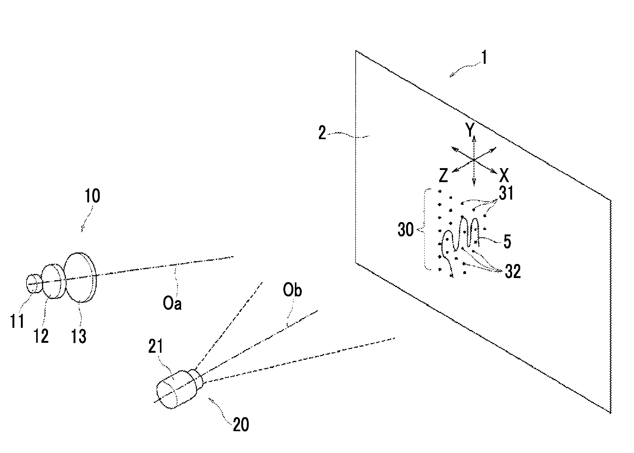
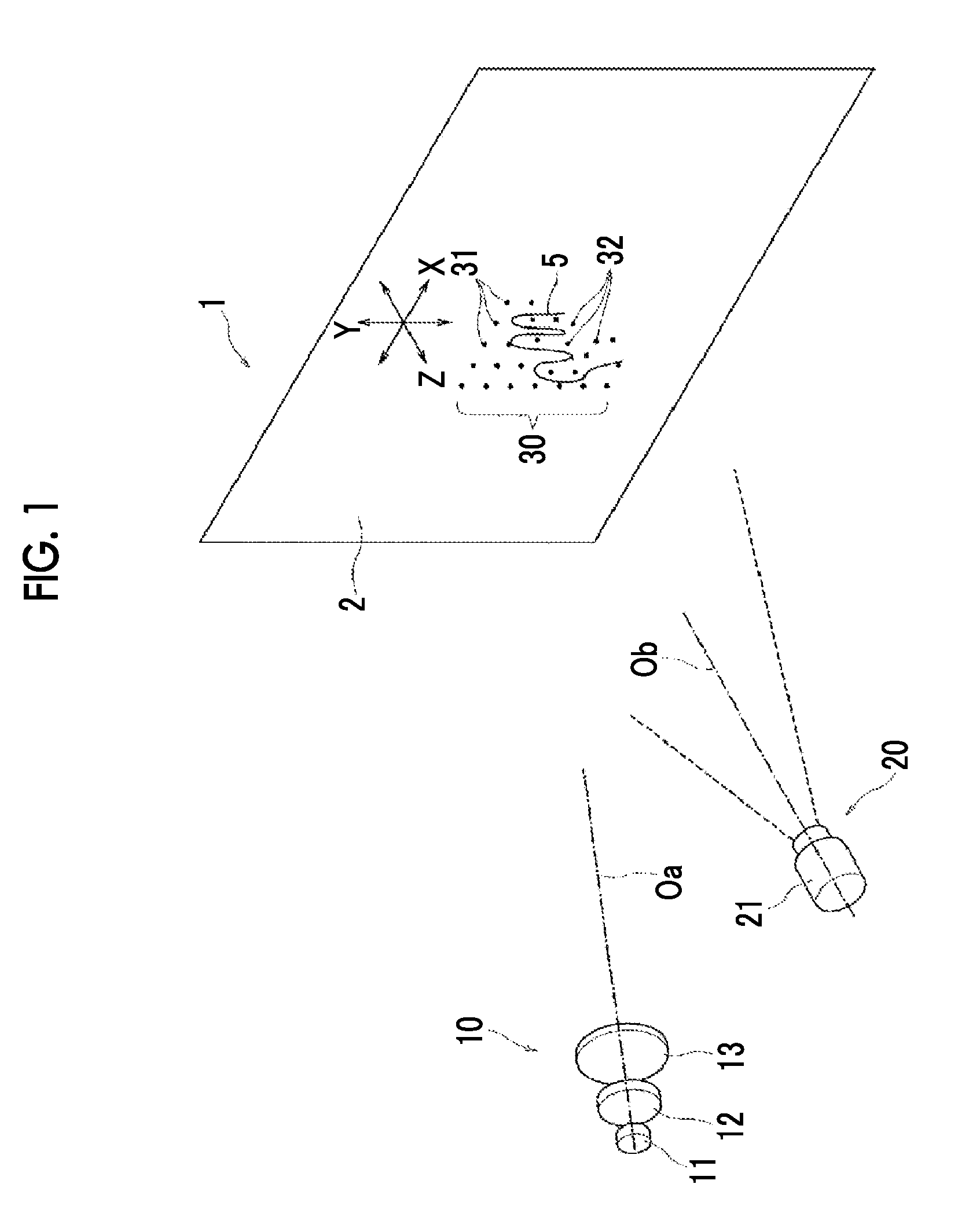
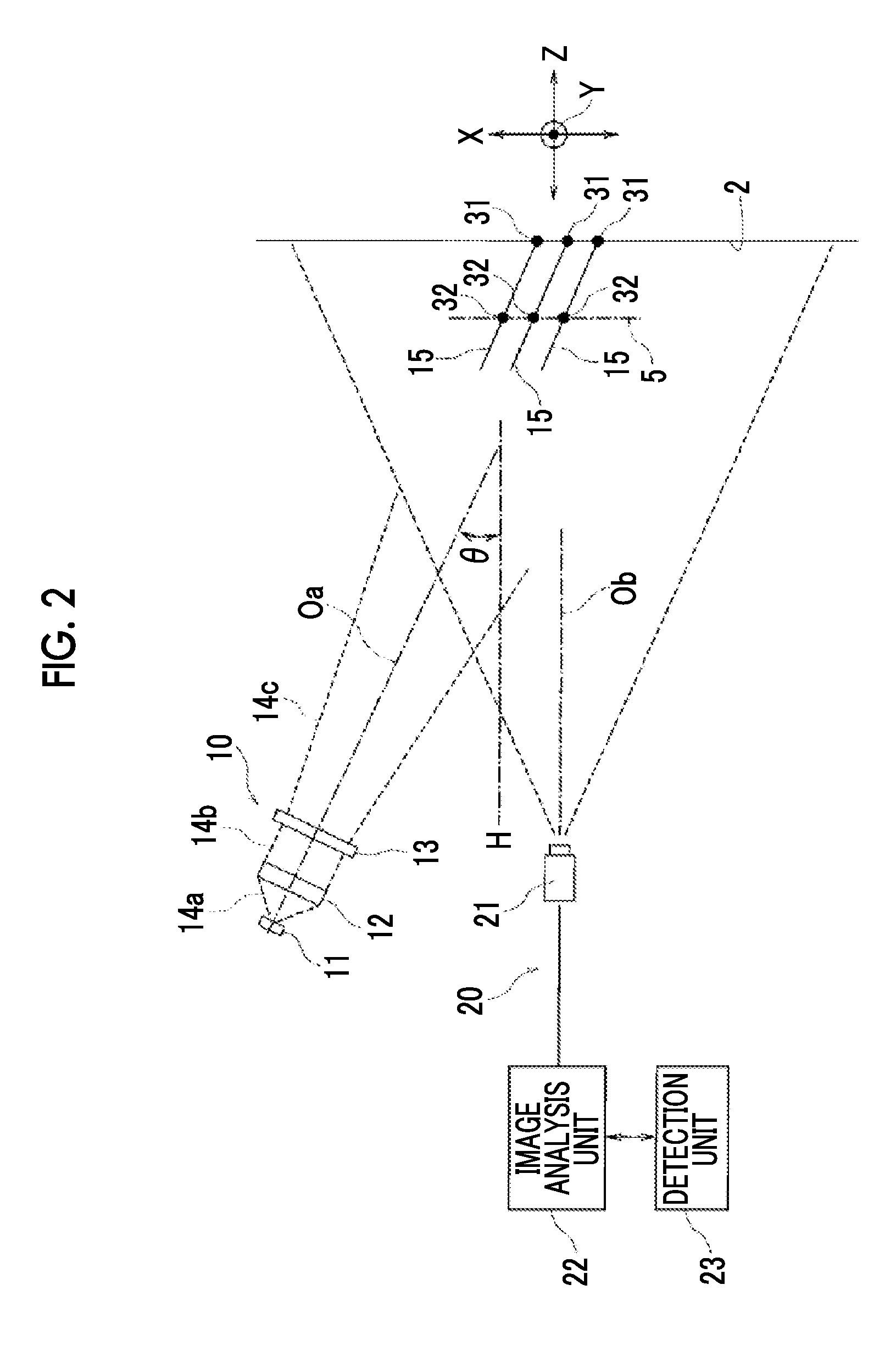
[0028]An object detection device 1 illustrated in FIGS. 1 and 2 includes a reference surface 2, and a light irradiation member 10 and an imaging member 20 facing the reference surface 2. While the reference surface 2 illustrated in FIGS. 1 and 2 is a plane, the reference surface 2 may be a surface having irregularities.

[0029]In FIGS. 1 and 2, X-Y-Z coordinates are illustrated as reference coordinates. An X-Y surface is a surface parallel to the reference surface 2, and an X-Z surface is a surface perpendicular to the reference surface 2. In the following description, an X direction is a horizontal direction in a light reception element of the imaging member 20 and the reference surface 2.

[0030]The light irradiation member 10 includes a laser light source 11 that is a coherent light source, a collimator lens 12 that converts a d...


PUM


Abstract

An object detection device includes a light source, an irradiation optical system that converts emitted light from the light source to measurement light having a predetermined pattern and emits the measurement light to a reference surface, and a light reception element that images the reference surface, and includes an imaging member that reads an image captured by the light reception element for each of a plurality of lines extending in a horizontal direction and arranged at predetermined intervals, and a detection unit that detects an object to be measured entering between a pattern forming unit and the reference surface based on image data from the imaging element, in which the pattern includes a plurality of division patterns arranged in the horizontal direction to correspond to the lines in the reference surface.

Description

CLAIM OF PRIORITY[0001]This application claims benefit of Japanese Patent Application No. 2015-047196 filed on Mar. 10, 2015, which is hereby incorporated by reference.BACKGROUND OF THE INVENTION[0002]1. Field of the Invention[0003]The present invention relates to an object detection device that irradiates an object to be measured with measurement light having a predetermined pattern and detects the object to be measured based on reflected light of the measurement light.[0004]2. Description of the Related Art[0005]In a three-dimensional measurement device disclosed in Japanese Patent No. 5001286, an illumination area is irradiated with a random speckle pattern in which a large number of spot lights generated by a light source are arranged at random, and the light response of the illumination area is detected by an image sensor. Displacement of the speckle pattern is detected in a pattern image obtained when the object to be measured has moved to the illumination area and a reference...

Claims


Application Information

Patent Timeline
Patent Type & Authority Applications(United States)
IPC IPC(8): G06T7/60G01B11/25G06T7/20G06K9/52G06K9/00
CPCG06T7/60G06K9/52G01B11/254G06T7/20G06K9/00335G01B11/2513G06V40/20
Inventor YAMASHITA, TATSUMARO
Owner ALPS ALPINE CO LTD
Why Eureka
Try Eureka