Interlocking building structure

a building structure and interlocking technology, applied in the direction of girders, walls, joists, etc., can solve the problems of large waste of materials, labor-intensive building construction, and many hours to complete, and achieve the effect of low material waste, easy assembly, and accurate construction

Inactive Publication Date: 2012-10-09
CLUFF JACOB
View PDF43 Cites 18 Cited by
  • Summary
  • Abstract
  • Description
  • Claims
  • Application Information

AI Technical Summary

Benefits of technology

[0016]Accordingly, the present invention overcomes many of the deficiencies and disadvantages of prior art wood frame building construction by providing interlocking building components and a unique method of construction that provides, when finished, a building that is relatively easy to assemble, results in little material waste and that provides a strong, self-supporting structure that is substantially true and plumb when completed. The present invention utilizes a novel puzzle-piece construction in order to join the various frame components resulting in strong joints and dimensionally accurate construction.

Problems solved by technology

Each step in the such conventional building construction is labor intensive and requires many hours to complete
Sheds on skids built using conventional construction techniques, however, are more likely to be out of true or plumb resulting in jammed windows and doors, are time consuming and labor intensive to build and result in substantial material waste when constructed.

Method used


Image

  • Interlocking building structure
  • Interlocking building structure
  • Interlocking building structure

Examples


Embodiment Construction

[0046]Those of ordinary skill in the art will realize that the following description of the present invention is illustrative only and not in any way limiting. Other embodiments of the invention will readily suggest themselves to such skilled persons.

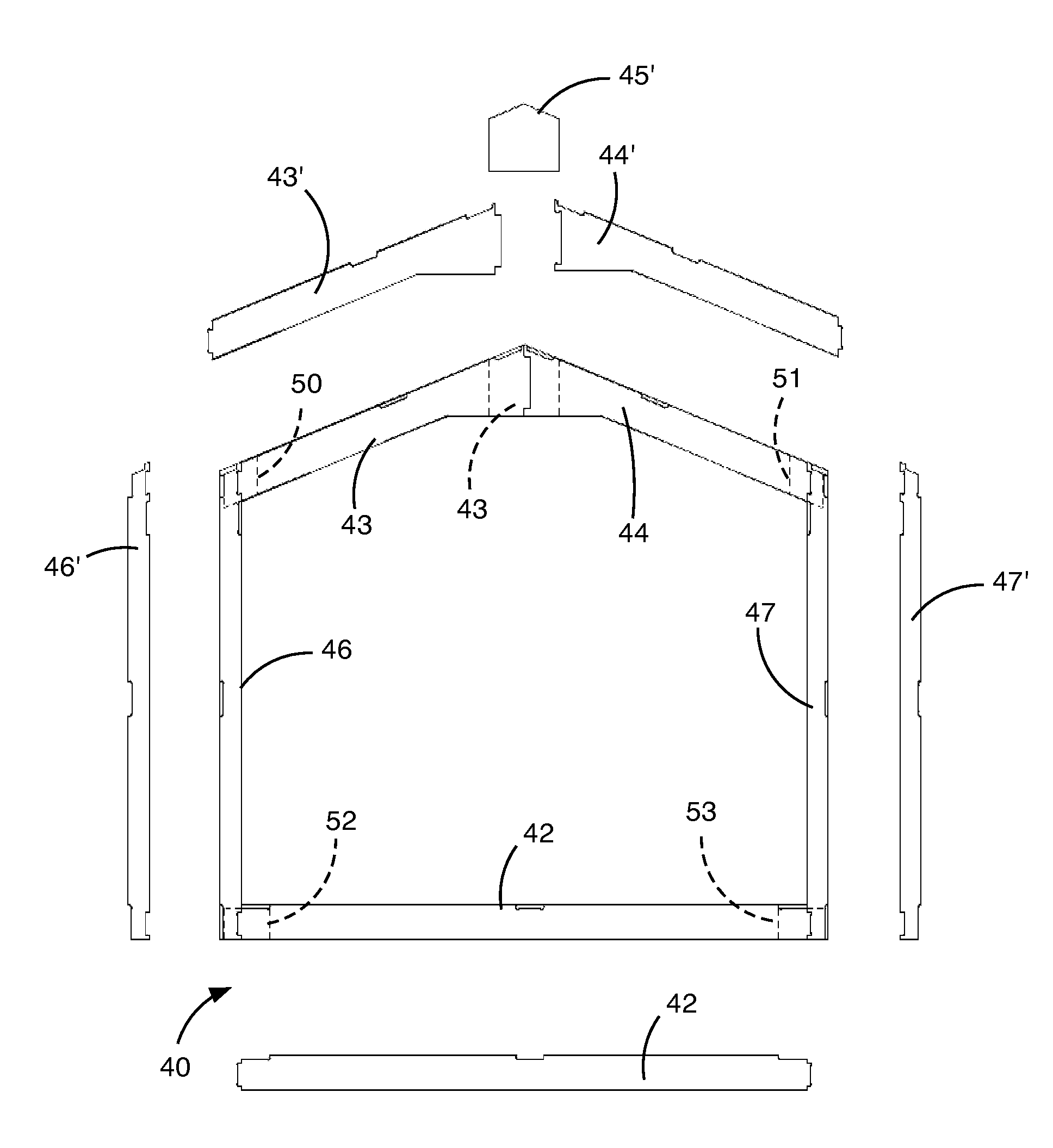
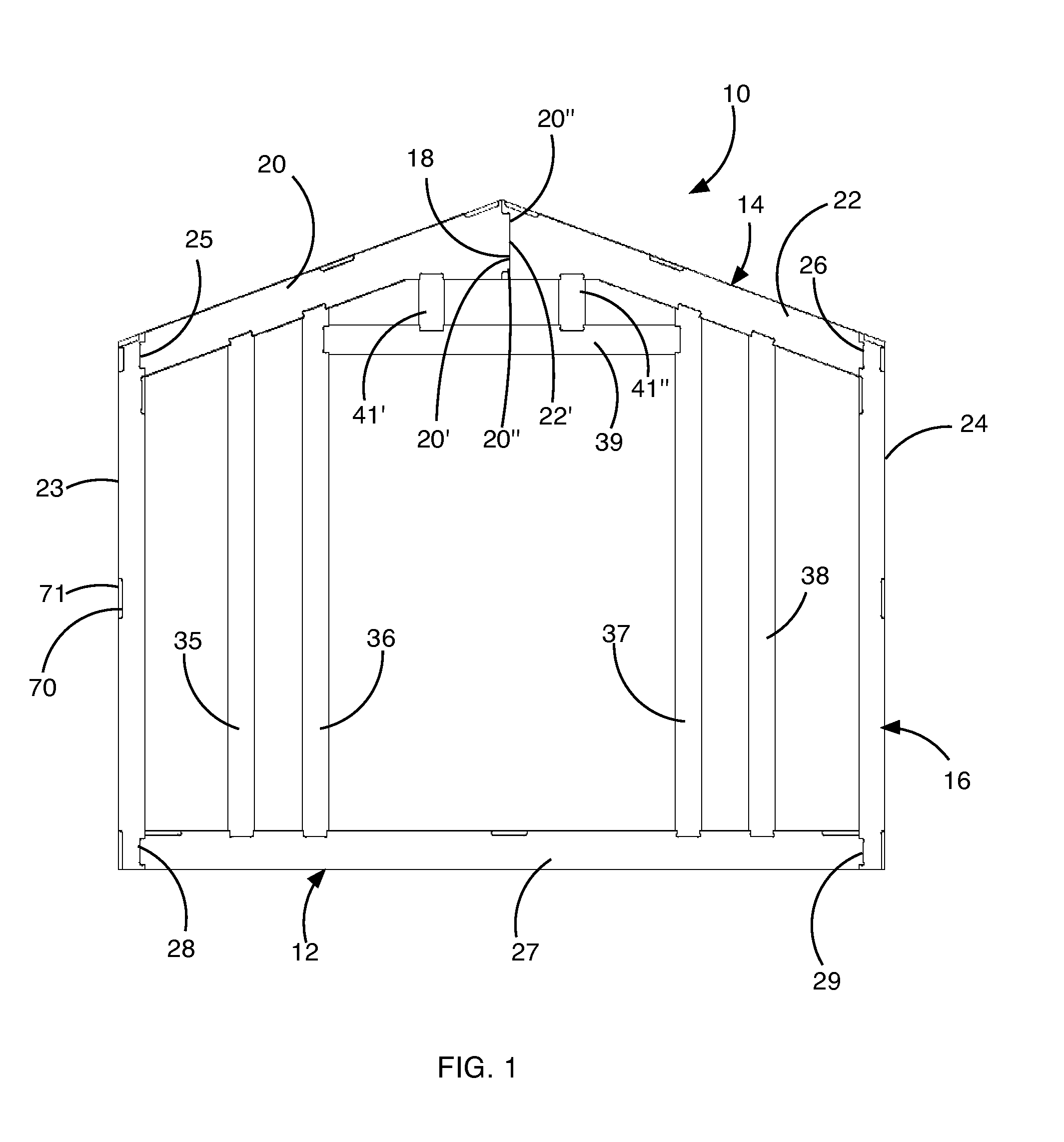
[0047]FIG. 1 illustrates a front view of a door side of a building frame, generally indicated at 10, in accordance with the principles of the preset invention. The frame 10 is comprised of a floor assembly 12, a roof assembly 14 and a plurality of wall assemblies, with front wall assembly 16 being visible. Each of the assemblies 12, 14 and 16 are comprised of a plurality of elongate members that are joined in an interlocking manner to secure adjacent members to one another. As will be described in more detail, the joints between adjacent members, such as joint 18 formed between members 20 and 22, have a jigsaw, puzzle-piece configuration. Specifically, the member 20 is provided with a protruding portion 20′ that is received in a recess ...


PUM


Abstract

A building structure having a plurality of frame assemblies joined together to form an internal frame structure for a building. Each of the frame assemblies includes a truss, a pair of vertical wall members and a floor joist. The truss is attached to respective top ends the vertical wall members at each end of the truss with interlocking joints in which the truss and vertical wall members are in substantially the same plane. Each vertical wall member is attached to the floor joist with interlocking joints. Each interlocking joint has a puzzle-piece configuration. Cross-members interconnect the frame assemblies in a spaced-apart manner. A floor panel is attached to the floor joists and exterior wall panels are attached to an exterior of the internal frame structure.

Description

CROSS-REFERENCE TO RELATED APPLICATION[0001]The present application claims priority to U.S. Provisional Application Ser. No. 61 / 258,469, filed on Nov. 5, 2009, the entirety of which is incorporated by this reference.BACKGROUND[0002]1. Field of the Invention[0003]The present invention relates generally to free standing building structures, and more specifically to a building structure that utilizes interlocking pieces to reduce material waste and to improve structural strength.[0004]2. State of the Art[0005]Most free-standing wood frame building structures, such as outdoor storage sheds, employ conventional wood frame construction techniques in which wood members, such as 2×4 planks are nailed or screwed together to form a floor, walls, roof and door when combined with plywood or wafer board sheets. Such construction generally requires the cutting of lumber to various sizes according to plan, assembly of the individual frame pieces to form frame components, the formation of a floor, ...

Claims


Application Information

Patent Timeline
Patent Type & Authority Patents(United States)
IPC IPC(8): E04B1/00E04B5/00E04B7/00
CPCE04B1/26E04C3/14E04B2001/2624E04B2001/2644
Inventor CLUFF, JACOB
Owner CLUFF JACOB
Why Eureka
Try Eureka