Digital mammography scanning system

a scanning system and digital technology, applied in the field of full-field digital mammography, can solve the problems of limiting the spatial resolution of the resulting image, film-based systems are subject to certain limitations, and full-field mammography systems are available, and achieve the effect of accurate construction of composite x-ray images and reduction of detector vibration

Active Publication Date: 2011-08-25
ADANI
View PDF2 Cites 19 Cited by
  • Summary
  • Abstract
  • Description
  • Claims
  • Application Information

AI Technical Summary

Benefits of technology

[0011]The present invention provides an improved digital mammography apparatus which allows for high resolution, full field breast imaging. In addition, the present invention reduces the effects of scattered radiation without requiring the use of a dose-inefficient grid. The present invention also provides a novel mechanism for acquiring image information as a X-ray detector is scanned across an area of interest and integrating the acquired information to yield a high fidelity composite image of the area of interest. Moreover, the present invention allows for automatic selection of a radiation filter, so that the filter can be selected based on particular X-ray imaging conditions to enhance the resulting image.
[0013]In order to accurately construct a composite X-ray image based on slot-scan imaging data, it is important to correlate imaging data acquisition to the X-ray detector scanning motion. In accordance with the present invention, this can be accomplished by mounting the vibration dampening mechanism to the pendulum and to the X-ray detector, which reduces vibration of the detector.
[0014]In one aspect, there is provided an apparatus for use in X-ray imaging an area of interest within a patient's breast, including a stationary frame; a rotating assembly mounted on the stationary frame, the rotating assembly including an axle assembly having a substantially horizontal axis of rotation (or an axis of rotation orthogonal to a patient's chest wall), an X-ray source that, in one embodiment, has a focal spot that approximately coincides with the horizontal axis of rotation; a collimator from which a fan-shaped X-ray beam exits towards a X-ray detector assembly, and a rotating assembly mechanically coupled to the detector assembly and pivoting about the horizontal axis of rotation. The detector assembly includes a linear X-ray detector for detecting the fan-shaped X-ray beam after the beam passes through the area of interest. The motor is mechanically coupled to the rotating assembly, which in turn bears the detector as well as X-ray tube with collimator attached to it, and enables arcuate movement of the detector assembly in a transverse direction. The motor enables rotational movement of the rotating assembly, and applies a force that is substantially offset from the horizontal axis of rotation. A distance between the detector assembly and the focal spot stays constant throughout the arcuate and rotational movements.

Problems solved by technology

More recently, full-field mammography systems have become available, though at considerable cost mostly due to the high cost of high resolution digital x-ray receivers based on flat panel X-ray detectors.
Film based systems are, however, subject to certain limitations.
For example, film granularity and random film screen noise limits the spatial resolution of the resulting image.
Furthermore, the time required to develop film images renders film-based systems less desirable for some applications, particular where, today, many patients (and physicians) wish to see the results of the diagnostic process immediately.
Cost is one major factor—a large-format mammographic X-ray receiver is very expensive and sometimes very sensitive to careless handling and environmental conditions, driving the cost of the overall device and its maintenance costs upwards.
However, such systems suffer from problems associated with flexing and mechanical deformations of the pendulum structure when the X-ray detector base on CCD is moving, which in turn causes a degradation of the image quality.

Method used


Image

  • Digital mammography scanning system
  • Digital mammography scanning system
  • Digital mammography scanning system

Examples


Embodiment Construction

[0031]Reference will now be made in detail to the preferred embodiment of the present invention, examples of which are illustrated in the accompanying drawings.

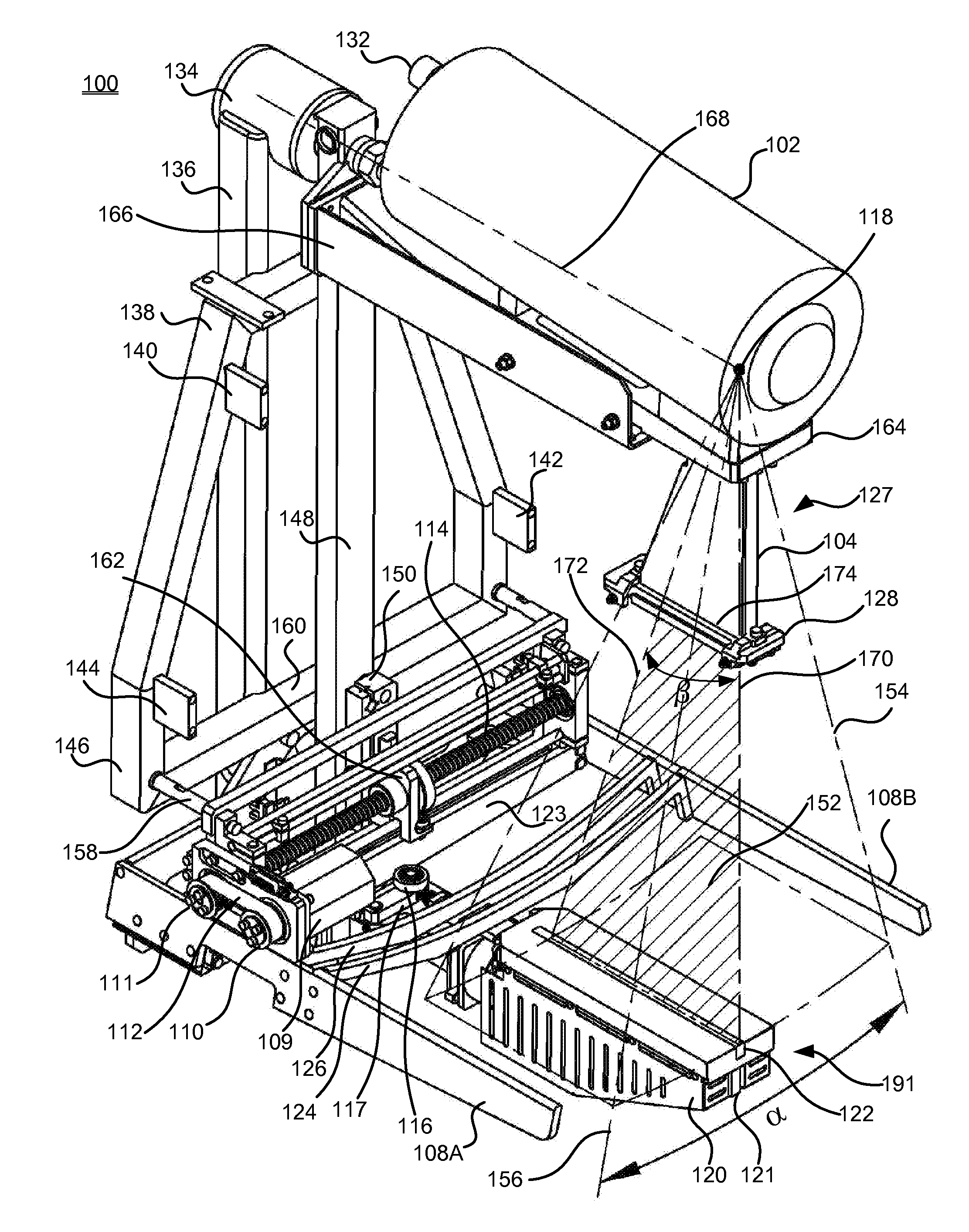
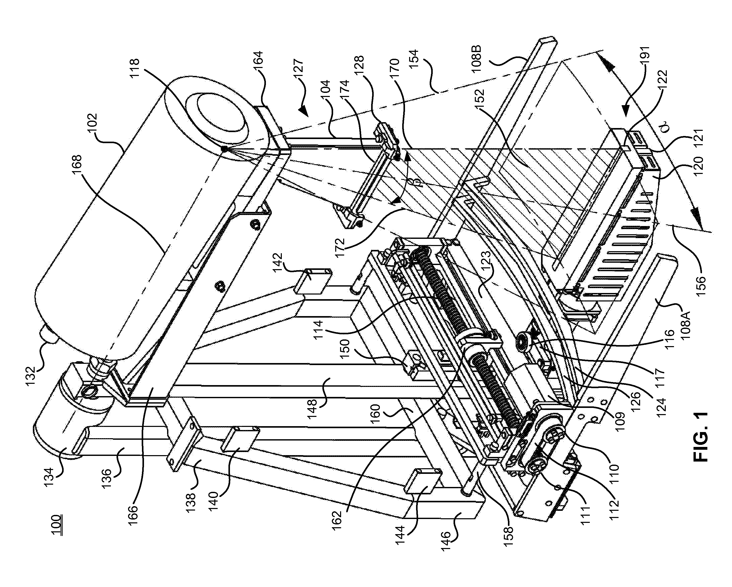
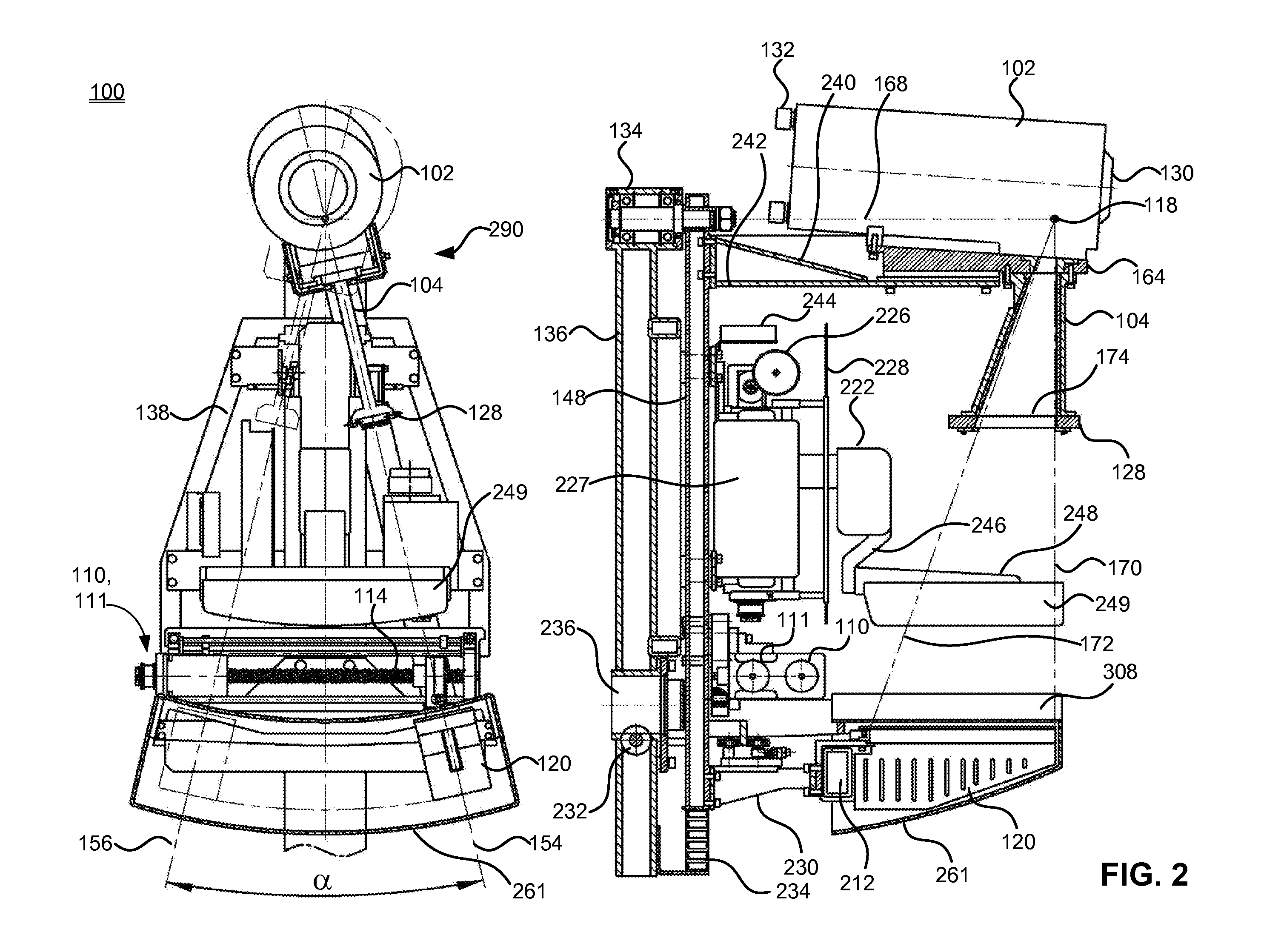
[0032]The mammography apparatus described herein is a full-field digital mammography system, designed to perform digital X-ray breast imaging for screening and diagnostic purposes (i.e., for early breast cancer detection). The digital full field mammography system is designed to be used in clinical practice to the same purpose, as a traditional analog (film-type) mammographic apparatus. The main features of an exemplary the full-field digital mammography system are (1) digital scanning X-ray image receiver with 54 micron pixel size; and (2) an anti-scatter grid free design, allowing for patient dose reduction with no loss of image quality.

[0033]Generally, the digital mammography scanning system uses scanning technology of producing digital X-ray images as follows:

[0034]An X-ray image is obtained by scanning of breast with a n...


PUM


Abstract

An apparatus for use in imaging an area of interest within a patient's body, including a stationary frame; a rotating assembly mounted on the stationary frame, the rotating assembly including an axle assembly having a substantially horizontal axis of rotation, an X-ray source having a focal spot that coincides with the horizontal axis of rotation; a collimator from which a fan-shaped X-ray beam exits towards a detector assembly, and a rotating frame mechanically coupled to the detector assembly and pivoting about the horizontal axis of rotation. The detector assembly includes a linear X-ray detector for detecting radiation of the fan-shaped X-ray beam after the beam passes through the area of interest, and is mechanically coupled to a motor that enables arcuate movement of the detector assembly in a transverse direction. The motor is mechanically coupled to the rotating assembly to enable rotational movement of the rotating assembly.

Description

CROSS-REFERENCE TO RELATED APPLICATIONS[0001]This application is a continuation of U.S. patent application Ser. No. 12 / 503,171, filed on Jul. 15, 2009, which incorporated herein by reference.BACKGROUND OF THE INVENTION[0002]1. Field of the Invention[0003]The present invention relates to full field digital mammography, in particular, to an apparatus for X-ray imaging a selected region of a patient's body by X-ray slot-scanning across the region and constructing a composite X-ray image of the region based on the scan. The invention has particular application to the field of mammography.[0004]2. Description of the Related Art[0005]Breast X-ray imaging is considered the most demanding of medical imaging procedures. With regard to spatial resolution, breast imaging specialists are now commonly interested in imaging lesions or masses that may require an imaging aperture that is about 50 microns in size or less. Contrast requirements are also demanding because lesions or masses to be visua...

Claims


Application Information

Patent Timeline
Patent Type & Authority Applications(United States)
IPC IPC(8): A61B6/02
CPCA61B6/06A61B6/4233A61B6/587A61B6/502A61B6/4488
Inventor LINEV, VLADIMIR N.
Owner ADANI
Why Eureka
Try Eureka