
Section-assembling bridge girder erection machine suitable for erecting bridges with minimum curve radii

A technology of curve radius and bridge erecting machine, which is applied in bridge construction, bridge erection/assembly bridge, etc. It can solve the problems that the bridge erecting machine cannot meet the erection requirements, uneven lateral load, etc., and achieves the convenience of adapting to variable span construction and construction The effect of high efficiency and high safety

Active Publication Date: 2013-04-10
CHINA RAILWAY 11TH BUREAU GRP +2
View PDF8 Cites 16 Cited by
  • Summary
  • Abstract
  • Description
  • Claims
  • Application Information

AI Technical Summary

Problems solved by technology

However, when the girder is erected in the curved section, the bridge erecting machine is waiting to erect the bridge span, the transverse center of the main girder assembly and the center line of the bridge to be erected will move a certain distance to the outside of the curve (depending on the radius of the curve, for 190 meters The curve can be moved by 650mm, which can reduce the uneven lateral load). Since the box girder in the curved section is arranged in a curve, the centerline of the box girder in each section from the pier to the mid-span direction is compared with the centerline of the bridge erecting machine. It gradually deviates to the outside of the curve. For the construction of the curve section, the usual bridge erecting machine cannot meet the erection requirements.

Method used


Image

  • Section-assembling bridge girder erection machine suitable for erecting bridges with minimum curve radii
  • Section-assembling bridge girder erection machine suitable for erecting bridges with minimum curve radii
  • Section-assembling bridge girder erection machine suitable for erecting bridges with minimum curve radii

Examples


Embodiment Construction

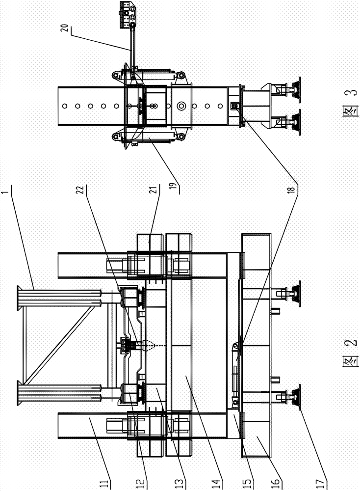
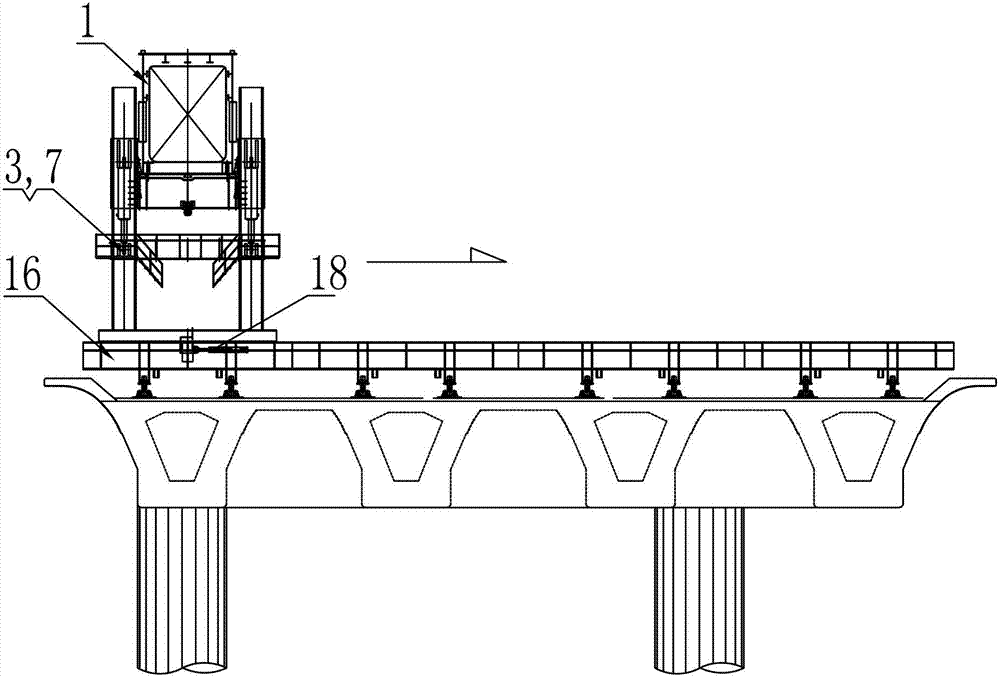
[0018] Below in conjunction with accompanying drawing, the present invention is further described: as figure 1 As shown, the segmental assembly bridge erecting machine suitable for the erection of extremely small curve radius bridges includes the main beam assembly 1, the front outrigger 8, the auxiliary outrigger 2, the No. 1 middle outrigger 7, and the No. 2 middle outrigger 3. Hoisting crane 5, middle suspension 4, hydraulic system 10, electrical system 9, the main girder assembly 1 is a single truss structure with simple structure and light weight, which is convenient for turning with a small radius. Such as figure 2 , 3 As shown, the No. 1 middle leg 7 or No. 2 middle leg 3 includes the inner column 11 of the middle leg, the upper crossbeam 12 of the middle leg turntable, the lower crossbeam 13 of the middle leg turntable, the support crossbeam 14 of the middle leg, the middle Outrigger connecting crossbeam 15, middle outrigger lower crossbeam 16, middle outrigger long...


PUM


Abstract

The invention relates to a section-assembling bridge girder erection machine suitable for erecting bridges with minimum curve radii. A girder assembly (1) is of a single-truss structure; No.1 middle support legs and No.2 middle support legs have the same structure, each middle support leg comprises a middle support leg-traversing mechanism, both ends of a middle support leg-traversing oil cylinder are respectively connected with a middle support leg-connecting crossbeam and a lower middle support leg crossbeam through pins, and the lower middle support leg crossbeam is of a horizontally assembled modularized structure; a rotary pin is welded on the top of the middle of a lower middle support leg turnplate crossbeam, and an upper middle support leg turnplate crossbeam is rotatably sleeved on the rotary pin. The section-assembling bridge girder erection machine can be hydraulically pushed to stably and accurately traverse, and can realize rapid, convenient and accurate construction in the process of erecting a bridge with a minimum curve radius and accurately align curved girder sections. The section-assembling bridge girder erection machine can swing girders, can pass through an opening along a curve during the construction of a bridge with a curve radius of 190 meters, and is suitable for construction in mountainous areas with complex terrains; for municipal construction in the downtown of a developed city, the site needed by the usage of the machine is small, and the affection of the machine on existing structures is little.

Description

technical field [0001] The invention relates to bridge erecting engineering machinery, in particular to a segmental assembly bridge erecting machine suitable for erecting bridges with extremely small curve radius. Background technique [0002] The bridge erecting machine is composed of four major parts: the main girder assembly, the supporting structure, the crane crane and the traverse luffing mechanism. The main girder assembly includes two parts, the main girder and the guide girder, which are the main bearing parts of the bridge erecting machine, and the front and rear of the guide girder are arranged symmetrically. The supporting structure consists of four parts, front, rear and middle outriggers, and the working load of the bridge erecting machine is transmitted to the bridge structure through the outriggers. [0003] The usual state of girder erection is: the railway bridge is set to assemble the high-level suspension segments first, and then the overall girder is pl...

Claims


Application Information

Patent Timeline
IPC IPC(8): E01D21/00
Inventor 向友仁赵晋华张丕界张旭东唐达昆王鹏韩阁孔凡华李青李伟奇王星
Owner CHINA RAILWAY 11TH BUREAU GRP
Learn More