
Lighting device with local photon supply area and photon distribution

A technology for lighting devices and areas, applied in light guides of lighting devices, components of lighting devices, lighting devices, etc., can solve problems such as complex storage and supply management, increased volume and cost, and no emission of luminous intensity

Active Publication Date: 2018-07-27
PEZHO SITROEN AUTOMOBILS SA
View PDF3 Cites 0 Cited by
  • Summary
  • Abstract
  • Description
  • Claims
  • Application Information

AI Technical Summary

Problems solved by technology

[0006] The first solution imposes a large number of electroluminescent diodes and leads to a higher probability of inversion of the electroluminescent diodes in terms of assembly and thus a higher probability of having light emitting devices that do not emit Strictly increasing luminous intensity
Also, this complicates the management of storage and supply on the assembly line
[0007] The second solution imposes the need to use control-strength electronic circuits, which increases bulk and cost
[0008] Furthermore, both solutions impose the need to use a large number of electroluminescent diodes in order to uniformly supply the entire input face of the light guide, which proves to be disadvantageous in terms of weight, volume and power consumption, and multiplies the probability of failure

Method used


Image

  • Lighting device with local photon supply area and photon distribution
  • Lighting device with local photon supply area and photon distribution

Examples


Embodiment Construction

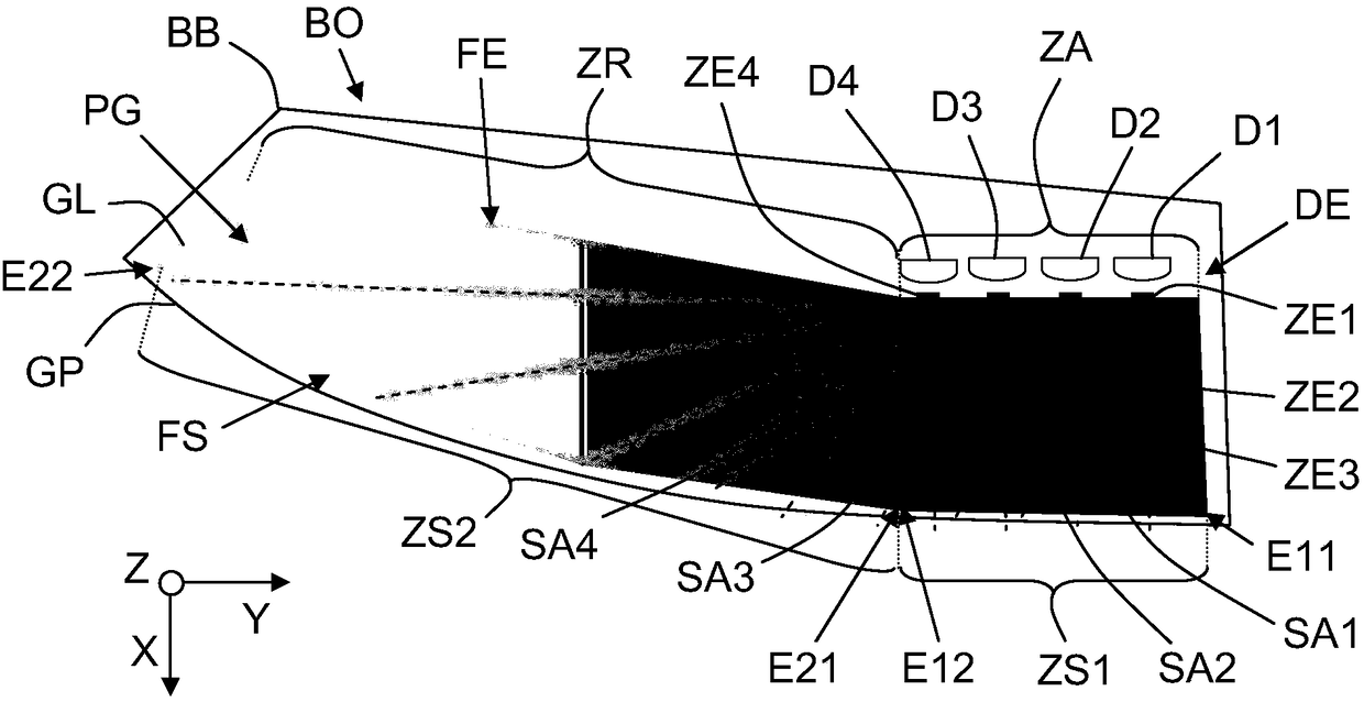
[0026] In particular, the object of the invention is to provide a lighting device DE with electroluminescent diodes Dj and light guides GL, which is capable of defining a luminous band BL of decreasing luminous intensity.

[0027] In what follows, as a non-limiting example, it is considered that the lighting device DE is intended for an optical unit BO fitted to a vehicle of motor type, for example a car. But the invention is not limited to this application. In fact, the lighting device DE may itself be a device (optionally comprising an inherent housing), or it may be part of another device than the optical unit of the vehicle. Therefore, the lighting device DE can be used as part of any means of transport (on land, sea (or river), or in the air), part of any facility (including industrial type facilities), part of any instrument (or system), and any part of a building.

[0028] Furthermore, in the following, as a non-limiting example, the optical unit BO (comprising at lea...


PUM


Abstract

The invention relates to a lighting device (DE), the lighting device includes electroluminescent diodes (D1-D4) and a flat light guide (GL), and the light guide includes a guiding unit (PG) arranged between an input surface (FE) and an output surface (FS). The input surface (FE) supplies photons to the guiding unit (PG), and the output surface (FS) sends the photons to the outside through guidance. The electroluminescent diodes (D1-D4) are all arranged to be opposite to input regions (ZE1-ZE4) defined in a supply region (ZA) of the input surface (FE), the supply region is opposite to the firstoutput region (ZS1) of the output surface (FS), the input region is configured to used for enabling received photons to be distributed in predefined angle sectors (SA1-SA4), so that luminous intensity decreasing progressively from a first output region (ZS1) is caused in a second output region (ZS2) of the output surface (FS), and the second output region is located beside the first output region(ZS1).

Description

technical field [0001] The invention relates to a lighting device, and more precisely to a lighting device comprising electroluminescent diodes which supply photons to a light guide and serve to ensure at least one lighting function. [0002] A "lighting device" is here understood to be a lighting device which can ensure at least one lighting function for lighting or signaling or (optionally decorative) lighting effects. Background technique [0003] In some fields, such as the field of vehicles (optionally of motor type), lighting devices are used to produce a light strip with a light from a first end of an output face to this same output face (with the The increasing strength of the second end portion opposite to the first end portion. This is, for example, when the lighting device is used to ensure night or day signal functions (brake lights, turn signals, reversing lights, position lights (or side lights or parking lights), or daytime running lights (or DRL "Daytime ru...

Claims


Application Information

Patent Timeline
Patent Type & Authority Applications(China)
IPC IPC(8): F21K9/20F21V8/00F21V23/00F21Y115/10
CPCF21K9/20F21V23/003F21V2200/00F21Y2115/10G02B19/0066G02B6/0058G02B19/0023F21S43/14F21S43/239F21S43/249G02B19/0028
Inventor M·博尔
Owner PEZHO SITROEN AUTOMOBILS SA
Learn More