
Capillary throttling device

A throttling device and capillary technology, applied in the direction of fluid circulation arrangement, high-efficiency adjustment technology, lighting and heating equipment, etc., can solve the problems of capillary ice blockage, unable to intercept air bubbles, etc., to avoid ice blockage, improve aging resistance and high resistance Low temperature characteristics, the effect of avoiding damage

Inactive Publication Date: 2018-07-27
安徽科凌仪器有限公司
View PDF0 Cites 1 Cited by
  • Summary
  • Abstract
  • Description
  • Claims
  • Application Information

AI Technical Summary

Problems solved by technology

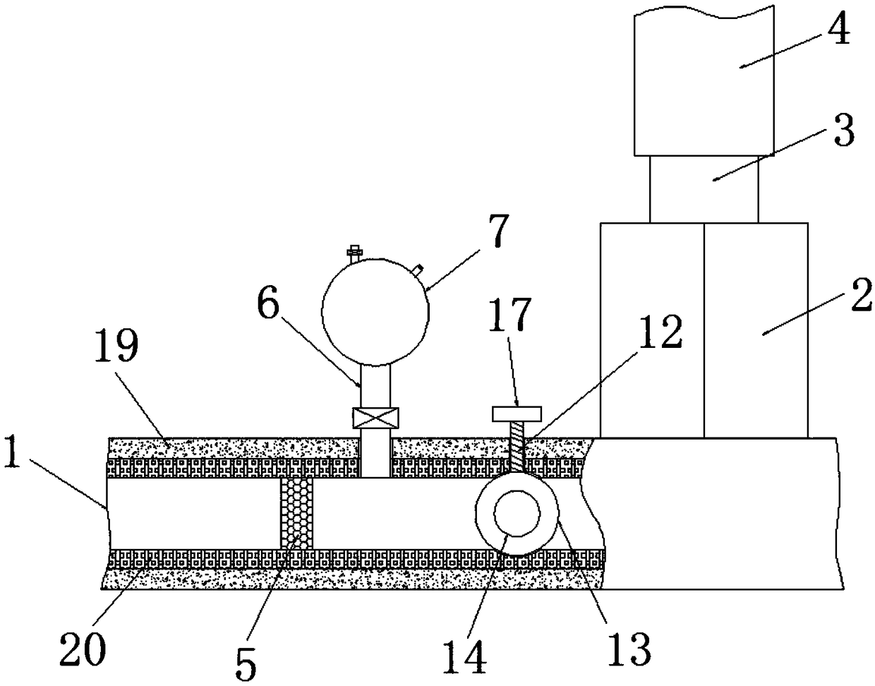
[0004] The purpose of the present invention is to solve the problem that the existing throttling device is only equipped with an electronic expansion valve, which cannot intercept the air bubbles, so that the liquid refrigerant accumulates in the standby indoor air conditioner, which easily leads to the problem of capillary ice blockage. A capillary throttling device

Method used


Image

  • Capillary throttling device
  • Capillary throttling device

Examples


Embodiment Construction

[0023] The following will clearly and completely describe the technical solutions in the embodiments of the present invention with reference to the accompanying drawings in the embodiments of the present invention. Obviously, the described embodiments are only some, not all, embodiments of the present invention.

[0024] In describing the present invention, it should be understood that the terms "upper", "lower", "front", "rear", "left", "right", "top", "bottom", "inner", " The orientation or positional relationship indicated by "outside", etc. is based on the orientation or positional relationship shown in the drawings, and is only for the convenience of describing the present invention and simplifying the description, rather than indicating or implying that the referred device or element must have a specific orientation, so as to Specific orientation configurations and operations, therefore, are not to be construed as limitations on the invention.

[0025] refer to Figure ...


PUM


Abstract

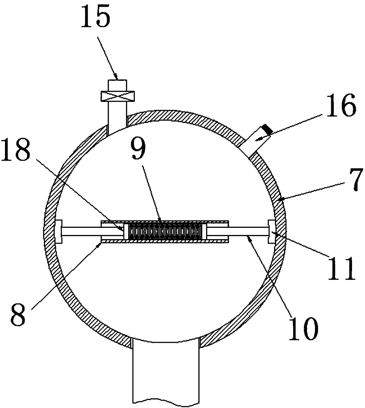
The invention discloses a capillary throttling device. The device comprises a refrigerant pipe, an electronic expansion valve and a capillary pipe. The electronic expansion valve is arranged on the outer wall of the refrigerant pipe. The capillary pipe is arranged on the electronic expansion valve. A filter element is fixedly arranged on the inner wall of the refrigerant pipe. The pipe wall of therefrigerant pipe communicates with a first water inlet pipe. The first water inlet pipe is located at the right side of the filter element. The end, away from the refrigerant pipe, of the first waterinlet pipe communicates with a water storage ball. A transverse pipe is arranged in the water storage ball. A spring is movably arranged in the transverse pipe. Slide blocks are fixedly arranged at the two ends of the spring correspondingly. Connecting rods are fixedly arranged at the ends, away from the spring, of the slide blocks correspondingly. Pressing plates are fixedly arranged at the ends, away from the slide blocks, of the connecting rods correspondingly. The side walls of the sides, away from the connecting rods, of the pressing plates are fixedly connected with the inner wall of the water storage ball. The capillary throttling device is convenient to operate, reverse rapid cleaning can be performed on the filter element, and remaining of air bubbles and impurities on the filterelement is avoided.

Description

technical field [0001] The invention relates to the technical field of air-conditioning accessories, in particular to a capillary throttling device. Background technique [0002] The throttling device is one of the four basic components necessary to realize the refrigeration cycle. In refrigeration equipment such as small air conditioners and refrigerators, capillary tubes are usually used as throttling devices. [0003] However, the existing throttling device only has an electronic expansion valve alone, which cannot intercept air bubbles, causing liquid refrigerant to accumulate in the standby indoor unit air conditioner, which easily leads to the problem of capillary ice blockage. Therefore, the present invention designs a capillary throttling device. Contents of the invention [0004] The purpose of the present invention is to solve the problem that the existing throttling device is only equipped with an electronic expansion valve, which cannot intercept the air bubbl...

Claims


Application Information

Patent Timeline
IPC IPC(8): F25B41/06F25B41/37
CPCF25B41/37Y02B30/70
Inventor 任庆华李明
Owner 安徽科凌仪器有限公司
Learn More