
Oil gas recovery device

A recovery device, oil and gas technology, applied in the recovery of liquid hydrocarbon mixture, petroleum industry, lighting and heating equipment, etc., can solve the problems of ice blockage or frost blockage, increased operation cost and maintenance cost, and poor water removal effect, etc., to achieve The effect of rapid cooling

Active Publication Date: 2021-01-05
深圳市奥图威尔科技有限公司
View PDF5 Cites 1 Cited by
  • Summary
  • Abstract
  • Description
  • Claims
  • Application Information

AI Technical Summary

Problems solved by technology

[0006] Although there are some oil and gas recovery systems that can prevent ice blockage in the prior art, they often go through multiple condensation processes, resulting in increased operating costs and maintenance costs of the system. In addition, due to the low heat exchange efficiency in each condensation process, the water removal effect No, it is easy to cause ice blockage or frost blockage in the process of oil and gas condensation, which reduces the efficiency of oil and gas recovery

Method used


Image

  • Oil gas recovery device
  • Oil gas recovery device
  • Oil gas recovery device

Examples


Embodiment Construction

[0033] The technical solutions in the embodiments of the present invention will be clearly and completely described below with reference to the accompanying drawings in the embodiments of the present invention. Obviously, the described embodiments are only a part of the embodiments of the present invention, but not all of the embodiments. The components of the embodiments of the invention generally described and illustrated in the drawings herein may be arranged and designed in a variety of different configurations. Thus, the following detailed description of the embodiments of the invention provided in the accompanying drawings is not intended to limit the scope of the invention as claimed, but is merely representative of selected embodiments of the invention. Based on the embodiments of the present invention, all other embodiments obtained by those skilled in the art without creative work fall within the protection scope of the present invention.

[0034] It should be noted ...


PUM


Abstract

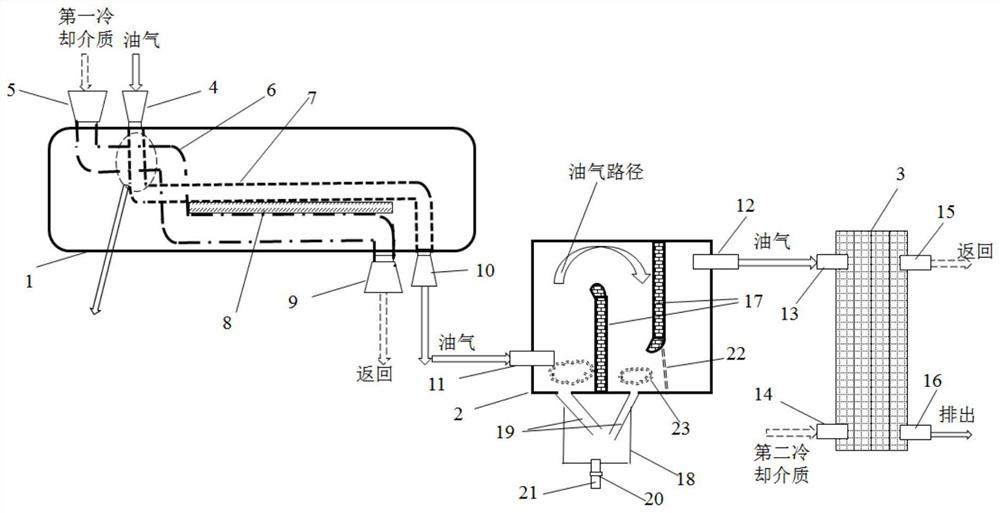
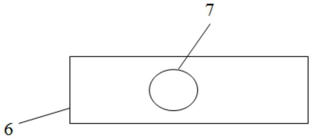
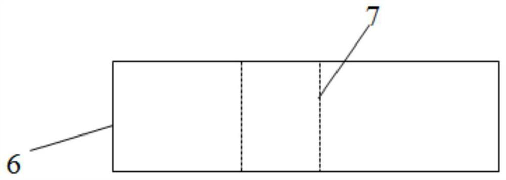
The invention relates to an oil gas recovery device. The oil gas recovery device comprises a water removal heat exchanger, a water separator and a condensate oil heat exchanger. The water removal heatexchanger comprises a first cooling medium conveying pipeline and an oil gas conveying pipeline which are located in the shell, the first cooling medium conveying pipeline and the oil gas conveying pipeline are provided with two sections of crossed parts, and the first cooling medium conveying pipeline and the oil gas conveying pipeline are provided with at least one part extending in parallel. Aheat conduction metal layer is arranged between the parallel extending parts, the bottom and the top of a shell part of the water separator are provided with at least two baffles which are verticallyarranged side by side and spaced by a certain distance, and the tops of the baffles are provided with arc-shaped structures bent in the oil-gas inlet direction. A second cooling medium is arranged inthe condensed oil heat exchanger. The oil gas recovery device is simple, and ice blockage can be prevented while oil gas recovery is guaranteed.

Description

technical field [0001] The invention relates to the technical field of an oil and gas recovery device, in particular to an oil and gas recovery device that efficiently recovers oil and gas and can prevent ice blockage. Background technique [0002] With the vigorous promotion of national environmental protection policies, oil and gas recovery devices are widely used in oil depots, gas stations and petrochemical fields. Oil and gas cannot be recovered well, which will pollute the environment while causing oil loss, and has greater harm. [0003] The condensing oil and gas recovery system is an energy-saving and environmentally friendly system that has been vigorously promoted in refineries and large oil storage depots in my country in recent years. The oil and water are condensed and separated out, and then the oil and water are separated to completely separate the oil, so as to achieve the recovery of oil products, and at the same time, the oil content in the final discharge...

Claims


Application Information

Patent Timeline
Patent Type & Authority Applications(China)
IPC IPC(8): C10G5/00C10G5/06F28D21/00
CPCC10G5/00C10G5/06F28D21/00F28D2021/0059Y02P70/10
Inventor 杜元新熊春波官建成陈璧鑫程平
Owner 深圳市奥图威尔科技有限公司
Learn More