
Structurally improved continuous material delivery pump

A technology for conveying pumps and materials, which is applied in the field of continuous conveying pumps for materials with improved structure, which can solve the problems of imperfect design of working structures, lower production costs, and limited conveying efficiency, so as to achieve a smaller friction coefficient, facilitate material conveying, and prevent The effect of residue buildup

Inactive Publication Date: 2016-09-21
TIANJIN SHIDA ELECTRIC POWER EQUIP
View PDF5 Cites 2 Cited by
  • Summary
  • Abstract
  • Description
  • Claims
  • Application Information

AI Technical Summary

Problems solved by technology

However, due to the imperfect design of the working structure of the prior art pneumatic conveying pumps, the conveying efficiency is very limited, and high pressure gas is required as the conveying power, which is not conducive to reducing production costs

Method used


Image

  • Structurally improved continuous material delivery pump
  • Structurally improved continuous material delivery pump

Examples


Embodiment Construction

[0020] The following will clearly and completely describe the technical solutions in the embodiments of the present invention with reference to the accompanying drawings in the embodiments of the present invention. Obviously, the described embodiments are only some of the embodiments of the present invention, not all of them.

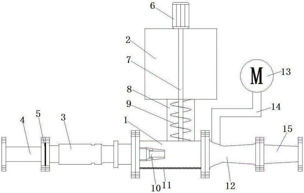
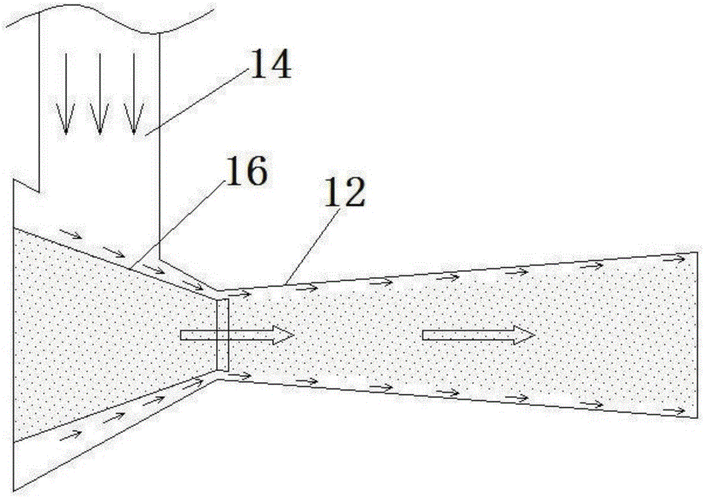
[0021] refer to Figure 1-2 , a material continuous conveying pump with an improved structure, comprising a storage bin 2, a pump body 1, an adjustable injector 3 and a venturi tube 12, the storage bin 2 is connected to the pump body 1 through a material inlet pipe 8, and the pump The body 1 is provided with a ring nozzle 10, the intake end of the pump body 1 is connected with the adjustable injector 3, and the first pipe sleeve 4 is added at the intake end of the adjustable injector 3, and the adjustable injector 3 and the first 4 pipe sleeves are provided with dust-proof nets 5 . The discharge end of the pump body 1 is connected to a Venturi tube 12,...


PUM


Abstract

The invention discloses a structurally improved continuous material delivery pump. The structurally improved continuous material delivery pump comprises a storage silo, a pump body, an adjustable ejector and a Venturi tube, wherein the storage silo is connected to the pump body by a material inlet pipe, an annular jet nozzle is arranged in the pump body, the gas inlet end of the pump body is connected with the adjustable ejector, a first pipe casing is additionally arranged at the gas inlet end of the adjustable ejector, and a dust gauze is arranged between the adjustable ejector and the first pipe casing; the discharge end of the pump body is connected with the Venturi tube; an auger is arranged in the material inlet pipe, a main shaft is fixedly arranged at the center of the auger in a penetrating manner and penetrates the storage silo to be in transmission connection with a motor arranged at the top of the storage silo; a discharge nozzle is arranged at the discharge end of the pump body and extends into the Venturi tube, and a slit ring is formed between the discharge nozzle and the Venturi tube; and the side surface of the Venturi tube is connected with a high-pressure blower by a high-pressure air pipe.

Description

technical field [0001] The invention relates to a conveying device, in particular to a material continuous conveying pump with an improved structure. Background technique [0002] In the field of material transportation, the technology of pneumatic conveying has developed rapidly. Continuous pneumatic conveying pumps are widely used in the transportation of powder materials, such as cement, mineral powder, metal powder, and fly ash. However, due to the imperfect design of the working structure of the prior art pneumatic conveying pumps, the conveying efficiency is very limited, and high-pressure gas is required as the conveying power, which is not conducive to reducing production costs. Contents of the invention [0003] The purpose of the present invention is to solve the shortcomings in the prior art, and propose a material continuous conveying pump with improved structure. [0004] In order to achieve the above object, the present invention adopts the following technic...

Claims


Application Information

Patent Timeline
IPC IPC(8): B65G53/08B65G53/36B65G53/58B65G53/34
CPCB65G53/08B65G53/34B65G53/36B65G53/58
Inventor 黄申王宝国孙计亮郭富强刘海波付仲楠马辉
Owner TIANJIN SHIDA ELECTRIC POWER EQUIP
Learn More