fixed focus lens
A fixed-focus lens and lens technology, which is applied in the field of optical systems, can solve problems such as large dispersion, serious purple fringing, and blurred lens imaging, and achieve clear and bright images, reduce processing difficulty and cost, and have a wide range of applications
- Summary
- Abstract
- Description
- Claims
- Application Information
AI Technical Summary
Problems solved by technology
Method used
Image
Examples
Embodiment 1
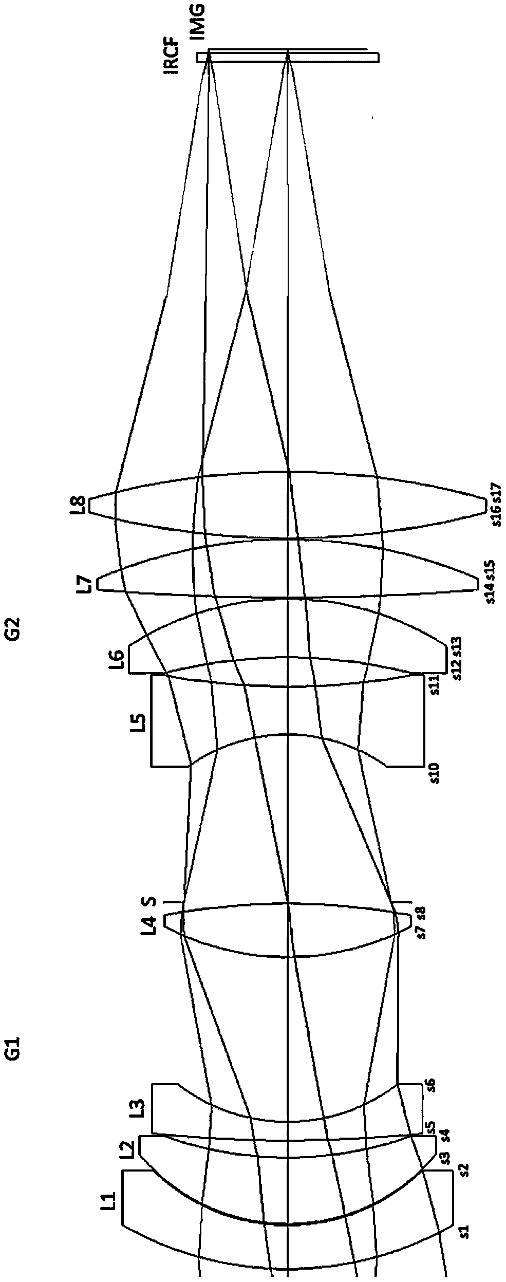
[0028] like figure 1 As shown, in this embodiment, the first lens group G1 with positive refractive power, the diaphragm STP, and the second lens group G2 with positive refractive power are arranged sequentially from the object plane side to the image plane side along the light incident direction, wherein : The first lens group G1 includes a first lens L1 with negative power, a second lens L2 with positive power, a third lens L3 with negative power, and a fourth lens L4 with positive power; The second lens group G2 includes a fifth lens L5 with negative power, a sixth lens L6 with positive power, a seventh lens L7 with positive power, and an eighth lens L8 with positive power.
[0029] Specifically, the overall focal length of the lens described in this embodiment is F=30 mm, the aperture number Fno=2, and the field of view Fov=26°.
[0030] The lens structure parameters of this embodiment are specifically as follows:
[0031] surface serial number surface type ...
Embodiment 2
[0040] like Figure 5 Shown is a schematic diagram of the structure of this embodiment. Compared with Example 1, this example adds a balance lens LX with negative refractive power behind the diaphragm STP. This lens can further balance the focal length allocation ratio of the two lens groups and reduce the spherical image of the lens in the example. Poor, so that the image quality can be further improved.
[0041] Specifically, the overall focal length of the lens described in this embodiment is F=27mm, the aperture number Fno=2.4, and the horizontal field of view Fov=22°.
[0042] The lens structure parameters of this embodiment are specifically as follows:
[0043]
[0044]
[0045] In this embodiment, the overall focal length ratios of the first lens group G1 , the second lens group G2 , and the fixed-focus lens are 1.09 and 1.02 respectively: at this time, the focal length ratios of the front and rear of the lens can balance the optical distortion caused by imaging...
Embodiment 3
[0053] like Figure 9 Shown is a schematic diagram of the structure of this embodiment. In this embodiment, on the basis of Embodiment 2, a first balanced lens LX1 with positive refractive power and a second balanced lens LX2 with positive refractive power are added in front and rear of the diaphragm STP respectively.
[0054] The first balanced lens LX1 adopts a glass material with a higher Abbe number, which further reduces the lateral chromatic aberration and spherical aberration of the lens compared with the previous two embodiments.
[0055] The balanced lens LX and the second balanced lens LX2 adopt the combination of negative and positive lenses, which not only balances the focal length ratio between the first lens group G1 and the second lens group G2, but also reduces the coma aberration and image curvature of the system, The imaging quality of the lens of this embodiment is further improved.
[0056] Specifically, the overall focal length of the lens described in t...
PUM
 Abstract
Description
Claims
Application Information
 - R&D
- Intellectual Property
- Life Sciences
- Materials
- Tech Scout
- Unparalleled Data Quality
- Higher Quality Content
- 60% Fewer Hallucinations
Browse by: Latest US Patents, China's latest patents, Technical Efficacy Thesaurus, Application Domain, Technology Topic, Popular Technical Reports.
© 2025 PatSnap. All rights reserved.Legal|Privacy policy|Modern Slavery Act Transparency Statement|Sitemap|About US| Contact US: help@patsnap.com


