
Electronic expansion valve

A technology of electronic expansion valve and valve body, which is applied in the direction of valve lift, valve details, valve device, etc. It can solve the problems of affecting the normal operation of the product, insufficient valve opening force, and reduced reliability of valve opening.

Active Publication Date: 2018-07-31
ZHEJIANG DUNAN MASCH CO LTD
View PDF7 Cites 10 Cited by
  • Summary
  • Abstract
  • Description
  • Claims
  • Application Information

AI Technical Summary

Problems solved by technology

[0007] The purpose of the present invention is to provide an electronic expansion valve to solve the problem that the current electronic expansion valve, especially the large-diameter valve, is prone to insufficient valve opening force and reduced valve opening reliability, which affects the normal operation of the product.

Method used


Image

  • Electronic expansion valve
  • Electronic expansion valve
  • Electronic expansion valve

Examples


Embodiment 1

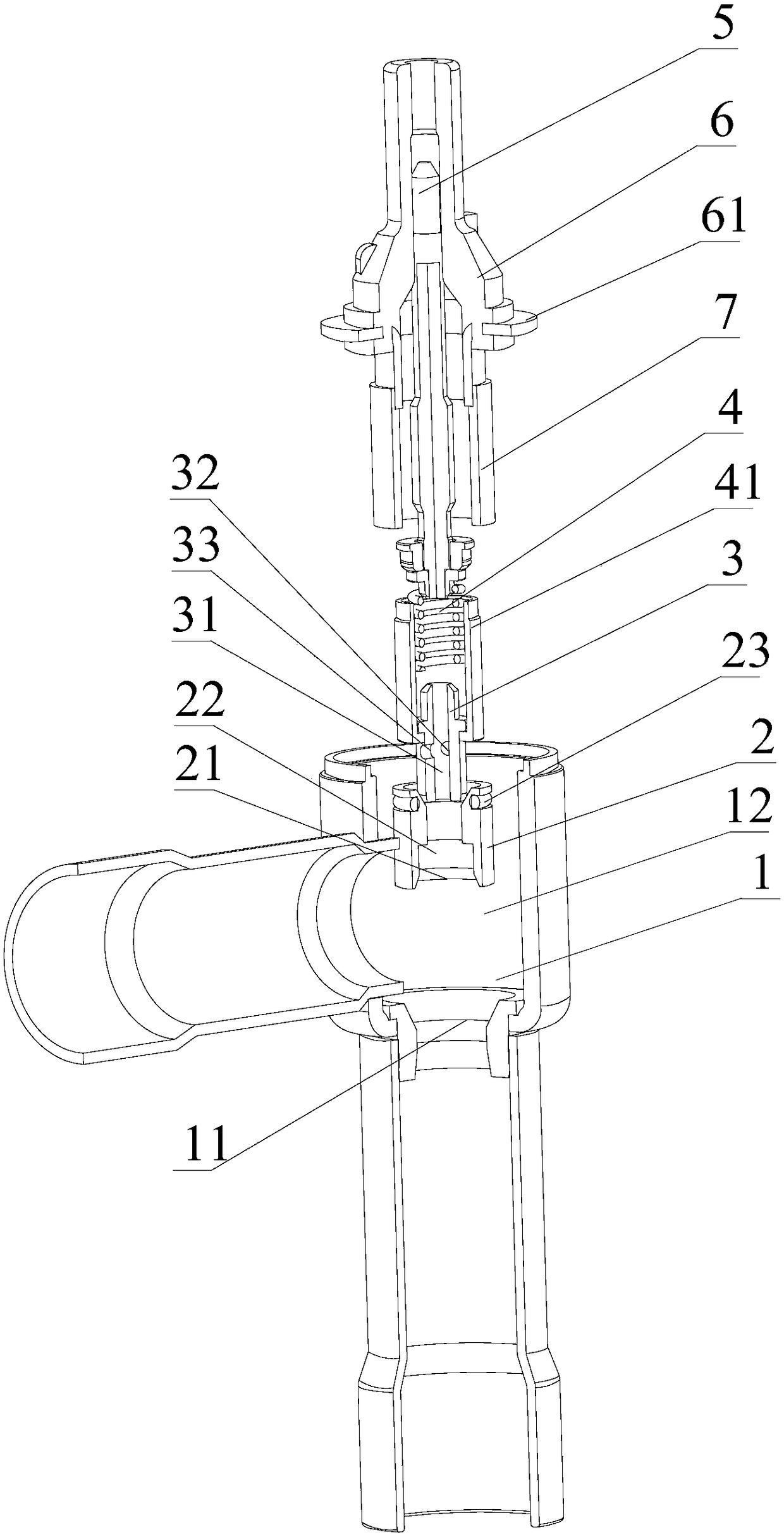
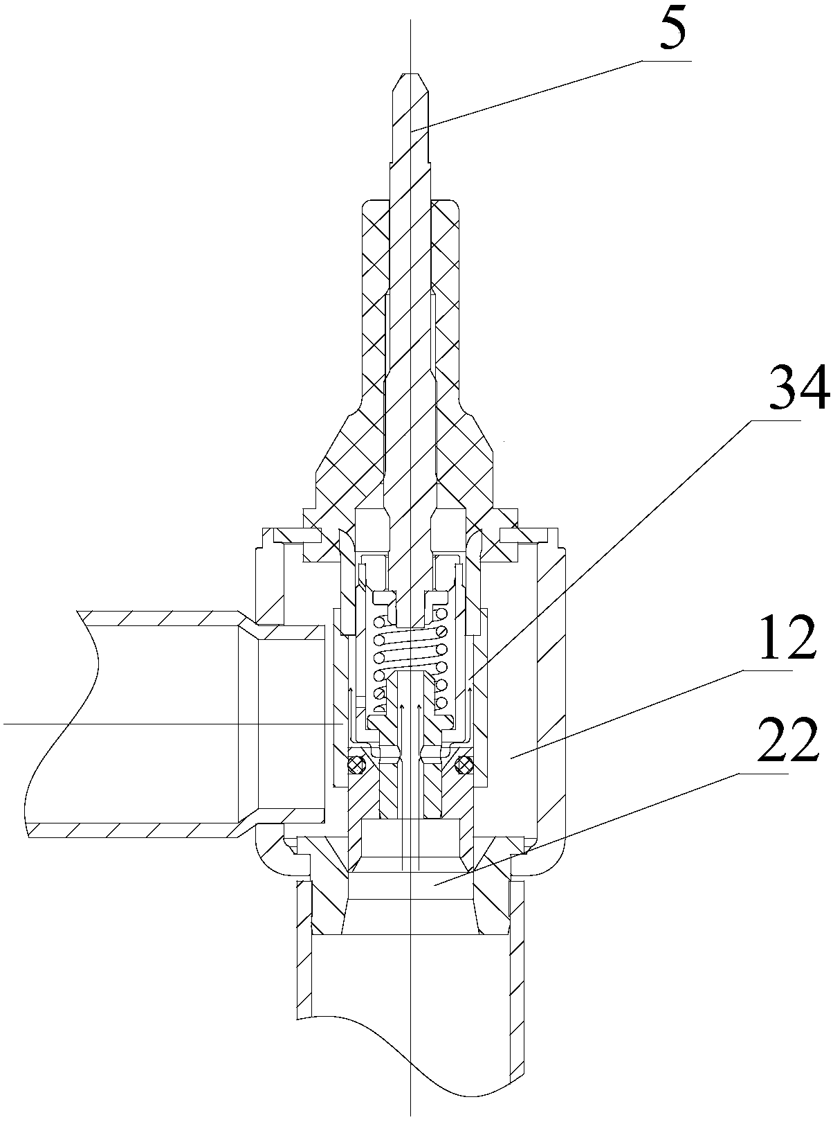
[0048] Please refer to Figure 2-Figure 9As shown, the embodiment of the present invention provides an electronic expansion valve, including: a valve body assembly, a valve head 2 , a valve needle shaft 3 , an elastic assembly, a screw rod 5 , a nut assembly and a guide sleeve 7 .

[0049] The valve body assembly includes a valve body 1 for connecting the first connecting end of the first external medium and a second connecting end for connecting the second external medium, and a housing 13 arranged on the valve body. The first connecting end in the valve head 1 The connecting end communicates with the first cavity 22 , and the second connecting end connects with the third cavity 12 . The spool shaft 3 is a through-hole structure; the balance channel includes the spool through hole 31 in the spool shaft 3 and the first balance set on the spool shaft 3 for connecting the spool through hole 31 and the second cavity 34 hole 32 and a second balancing hole 33 . The elastic assemb...

Embodiment 2

[0062] Such as Figure 10-Figure 13 , The embodiment of the present invention provides an electronic expansion valve, comprising: a valve body assembly, a valve head 2 , a valve needle shaft 3 , an elastic assembly, a screw rod 5 , a nut assembly and a guide sleeve 7 .

[0063] The valve body assembly includes a valve body 1 for connecting the first connecting end of the first external medium and a second connecting end for connecting the second external medium, and a housing 13 arranged on the valve body. The first connecting end in the valve head 1 The connecting end communicates with the first cavity 22 , and the second connecting end connects with the third cavity 12 . The spool shaft 3 is a through-hole structure; the balance channel includes the spool through hole 31 in the spool shaft 3 and the first balance set on the spool shaft 3 for connecting the spool through hole 31 and the second cavity 34 hole 32 and a second balancing hole 33 . The elastic assembly includes ...

Embodiment 3

[0075] Such as Figure 14-Figure 16 , The embodiment of the present invention provides an electronic expansion valve, comprising: a valve body assembly, a valve head 2 , a valve needle shaft 3 , an elastic assembly, a screw rod 5 , a nut assembly and a guide sleeve 7 .

[0076] The valve body assembly includes a valve body 1 for connecting the first connecting end of the first external medium and a second connecting end for connecting the second external medium, and a housing 13 arranged on the valve body. The first connecting end in the valve head 1 The connecting end communicates with the first cavity 22 , and the second connecting end connects with the third cavity 12 . The spool shaft 3 is a through-hole structure; the balance channel includes the spool through hole 31 in the spool shaft 3 and the first balance set on the spool shaft 3 for connecting the spool through hole 31 and the second cavity 34 hole 32 and a second balancing hole 33 . The elastic assembly includes ...


PUM


Abstract

The invention provides an electronic expansion valve. The electronic expansion valve comprises a valve body assembly, a valve needle shaft and a guide sleeve, wherein the bottom of the valve body assembly is provided with a valve seat with an internal conical valve port, and the valve body assembly is internally provided with a valve body corresponding to the valve port of the valve seat; the valve body is of a through hole structure and is internally provided with a first cavity; the valve needle shaft is fixedly connected with an inner ring of the valve body; an elastic assembly is arrangedon an outer ring of the top area of the valve needle shaft; the top of the elastic assembly is connected with a screw rod; a nut assembly is arranged outside the screw rod; the guide sleeve is in sealing and sliding connection with the outer ring of the valve body; the top of the guide sleeve is connected with the nut assembly; the inner ring of the guide sleeve, the top wall of the valve body andthe outer ring of the valve needle shaft form a second cavity; the valve needle shaft is provided with a balance channel communicating with the second cavity and the first cavity. The pressure of a valve element to the interiors of the cavities of the valve body is balanced, the loading capacity of a rotor is effectively reduced, the valve opening capacity of sample pieces is improved, and the valve element has the obvious advantages on a large-aperture valve body.

Description

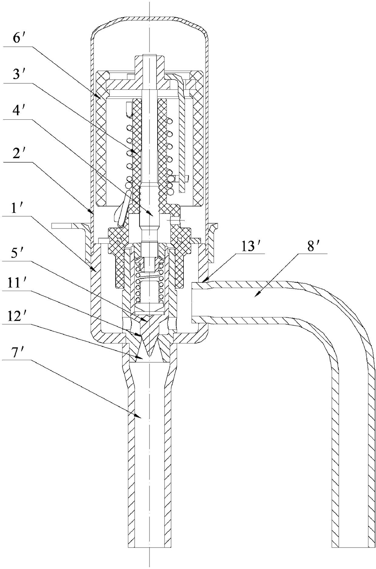
technical field [0001] The invention relates to an electronic expansion valve. Background technique [0002] As a new type of control element, the electronic expansion valve has already broken through the concept of the throttling mechanism. It is an important link in the intelligentization of the refrigeration system, an important means and guarantee for the real realization of the optimization of the refrigeration system, and an important part of the mechanical and electrical integration of the refrigeration system. Symbols have been used in more and more fields. [0003] Combine now figure 1 To illustrate the specific structure of the direct-acting electronic expansion valve, the electronic expansion valve includes a valve seat 1', a housing 2' welded with the valve seat 1' to form a valve cavity; The guide nut 3', the valve stem 4' connected with the guide nut 3' by screw transmission, one end of the valve stem 4' is provided with a valve needle 5', and the other end i...

Claims


Application Information

Patent Timeline
Patent Type & Authority Applications(China)
IPC IPC(8): F16K1/00F16K1/32F16K1/38F16K27/02F25B41/06F25B41/34
CPCF16K1/00F16K1/32F16K1/38F16K27/0254F25B41/34F25B41/31Y02B30/70
Inventor 王定军詹少军胡煜刚
Owner ZHEJIANG DUNAN MASCH CO LTD
Learn More