Self-adaptive gravity high-rise fire escape rope forced landing device

An adaptive and gravity technology, applied in life-saving equipment, building rescue, etc., can solve the problems of delayed fire escape, low escape efficiency, and inability to adapt to the weight of the crash-lander.

Pending Publication Date: 2018-08-03
SHENZHEN WEIXINGSHUN TECH CO LTD
View PDF2 Cites 2 Cited by
  • Summary
  • Abstract
  • Description
  • Claims
  • Application Information

AI Technical Summary

Problems solved by technology

Among them, the fixed resistance type high-rise fire escape forced landing device has a fixed resistance when the rope is pulled out. This method cannot well adapt to the different weights of the forced landings, which will lead to slow decline for those with small weights and slow down for those with heavy weights. The rapid descent, or the lack of gravity due to the small body weight directly lead to the result of being unable to make a forced landing
The resistance manual adjustable high-rise fire escape emergency landing device generally needs to set the resistance when the rope is pulled out according to its own weight, or often requires two people to cooperate to complete it, one is tied to the rope to descend, and the other manually controls the rope in real time. Although this manually adjustable high-rise fire escape forced landing device can adjust the resistance when the rope is pulled out according to the weight of the forced lander, so that the landing speed of the forced lander can be controlled to a certain extent, but in the emergency of a fire Under such circumstances, people usually cannot make accurate judgments and quickly operate equipment that is not frequently used, which makes the escape efficiency low and easily delays the timing of escape in a fire

Method used


Image

  • Self-adaptive gravity high-rise fire escape rope forced landing device
  • Self-adaptive gravity high-rise fire escape rope forced landing device
  • Self-adaptive gravity high-rise fire escape rope forced landing device

Examples


Embodiment Construction

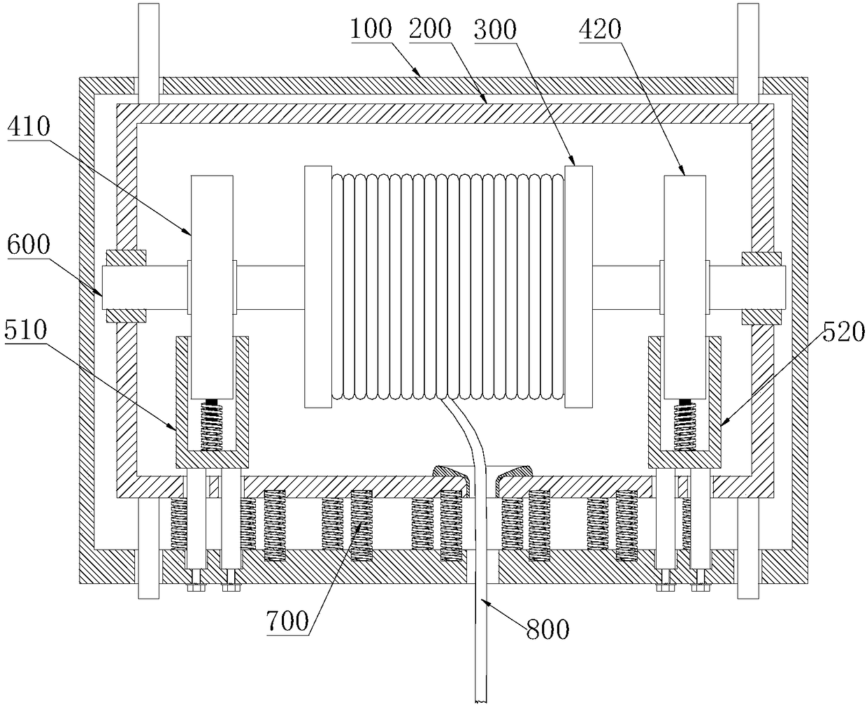
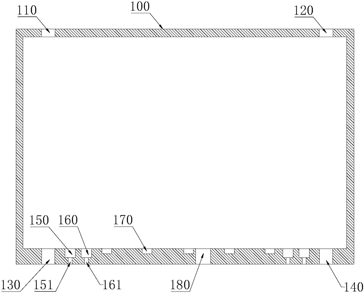
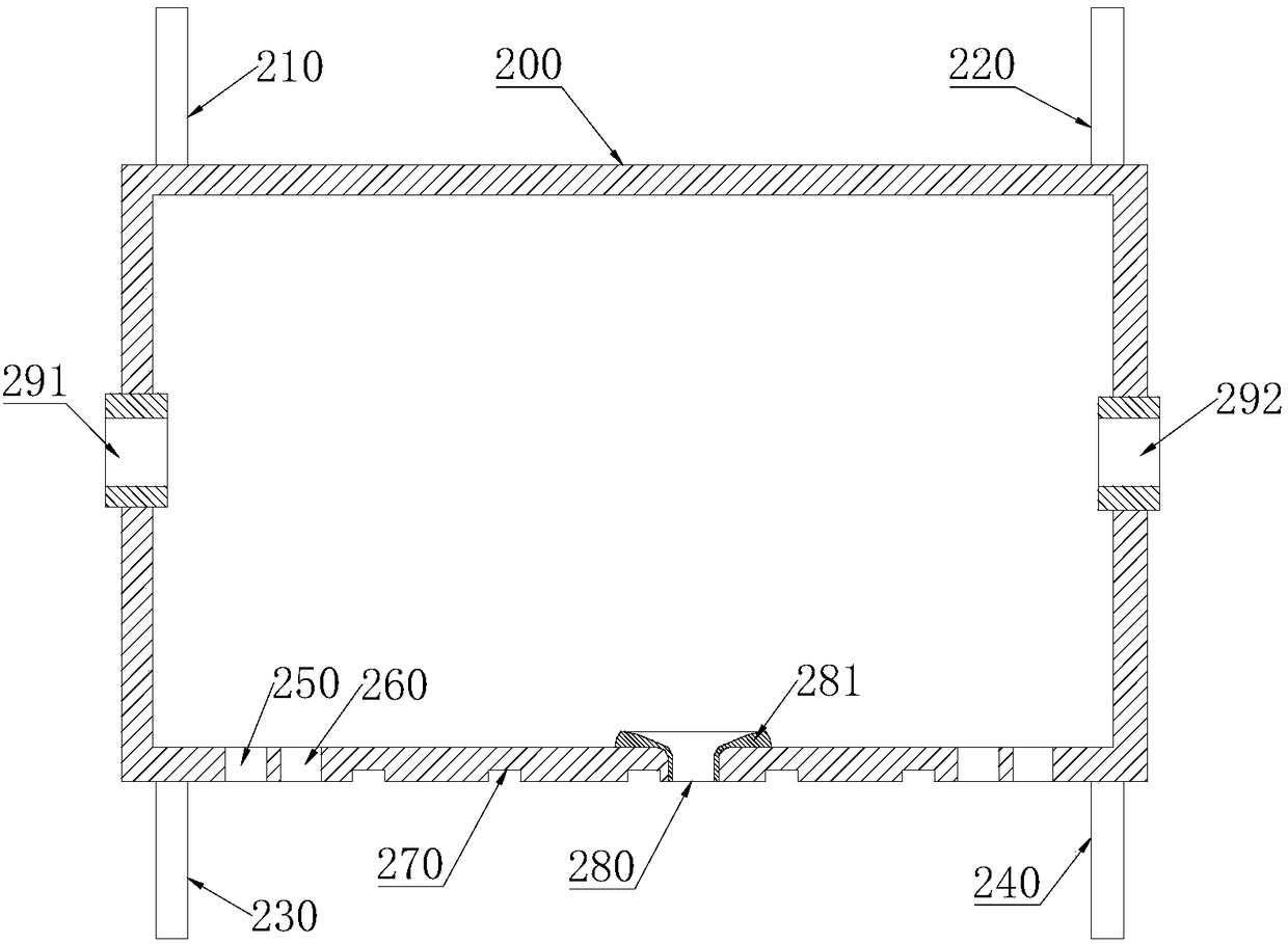
[0048] In this patent document, the following discussed Figure 1-6The various examples and examples used to describe the principles or methods of the present disclosure are by way of illustration only and should not be construed in any way to limit the scope of the present disclosure. Those skilled in the art should understand that the principles and methods of the present disclosure may be implemented in any suitably arranged mechanical structure. Preferred embodiments of the present disclosure will be described below with reference to the accompanying drawings. In the following description, detailed descriptions of well-known functions or configurations will be omitted so as not to obscure the subject matter of the present disclosure with unnecessary detail. Also, the terms used herein will be defined according to the functions of the present invention. Therefore, the terms may be different according to user's or operator's intention or usage. Therefore, the terms used h...


PUM


Abstract

The invention relates to a self-adaptive gravity high-rise fire escape rope forced landing device. The self-adaptive gravity high-rise fire escape rope forced landing device comprises an outer shell,an inner shell embedded into the outer shell, an elastic part and at least one brake part. The inner shell and the outer shell are slidably connected in at least one direction. The elastic part is connected to the inner shell and the outer shell to apply an acting force opposite to the sliding direction of the inner shell and the outer shell. The brake part comprises a movable part connected to arope winding plate to conduct a torque and a brake part for applying a reverse action force to the movable part. The brake part is connected to the outer shell, the movable part is connected to the inner shell, or the brake part is connected to the inner shell, and the movable part is connected to the outer shell, so that the brake part and the movable part shifts and / or deviates along with slideof the inner shell and the outer shell so as to change the action force between the brake part and the movable part. Therefore, the resistance of a rope pulled out in the device is positively relatedto the weight of a forced lander, and the falling speed difference of forced landers with different weights is controlled to decrease.

Description

technical field [0001] The invention relates to the field of security technology, in particular to an adaptive gravity high-rise fire escape rope forced landing device. Background technique [0002] At present, the traditional high-rise fire escape forced landing device mainly includes two kinds of fixed resistance type and resistance manual adjustable type. Among them, the fixed resistance type high-rise fire escape forced landing device has a fixed resistance when the rope is pulled out. This method cannot well adapt to the different weights of the forced landings, which will lead to slow decline for those with small weights and slow down for those with heavy weights. The rapid descent, or the lack of gravity due to the small body weight directly lead to the failure to make a forced landing. However, the resistance manual adjustable high-rise fire escape emergency landing device generally needs to set the resistance when the rope is pulled out according to its own weight,...

Claims


Application Information

Patent Timeline
Patent Type & Authority Applications(China)
IPC IPC(8): A62B1/10A62B1/18
CPCA62B1/10A62B1/18
Inventor 利友荣
Owner SHENZHEN WEIXINGSHUN TECH CO LTD
Why Eureka
Try Eureka