
Deep sea low-noise variable pump

A low-noise, variable-displacement pump technology, applied in the field of underwater hydraulics, can solve the problems of low operating pressure, small pressure pulsation, and large flow pulsation of screw pumps, and achieve the effects of improving service life, wide application range, and large variable range

Active Publication Date: 2021-02-12
CHINA SHIP SCIENTIFIC RESEARCH CENTER (THE 702 INSTITUTE OF CHINA SHIPBUILDING INDUSTRY CORPORATION)
View PDF6 Cites 0 Cited by
  • Summary
  • Abstract
  • Description
  • Claims
  • Application Information

AI Technical Summary

Problems solved by technology

Gear pumps mainly have the advantages of simple structure, good processing technology, small size, wear resistance, strong anti-pollution ability, etc., but there are also disadvantages such as low volumetric efficiency at low speeds, generally high operating speed and high noise
[0004] The screw pump mainly has the advantages of small pressure pulsation, low noise, high volumetric efficiency, and strong anti-pollution ability, but the screw pump has disadvantages such as difficult processing and low operating pressure.
[0005] The vane pump has the advantages of uniform flow, stable movement, low noise, and small volume, but the vane pump is prone to cause the vane to be stuck, and has high requirements for the cleanliness of the oil
[0006] The plunger pump has various structural forms, and has the advantages of high working pressure, high efficiency, and convenient variable variables, but because of its large flow pulsation, it will emit a lot of noise during operation

Method used


Image

  • Deep sea low-noise variable pump
  • Deep sea low-noise variable pump
  • Deep sea low-noise variable pump

Examples


Embodiment Construction

[0031] The specific implementation manner of the present invention will be described below in conjunction with the accompanying drawings.

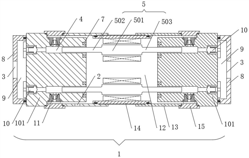
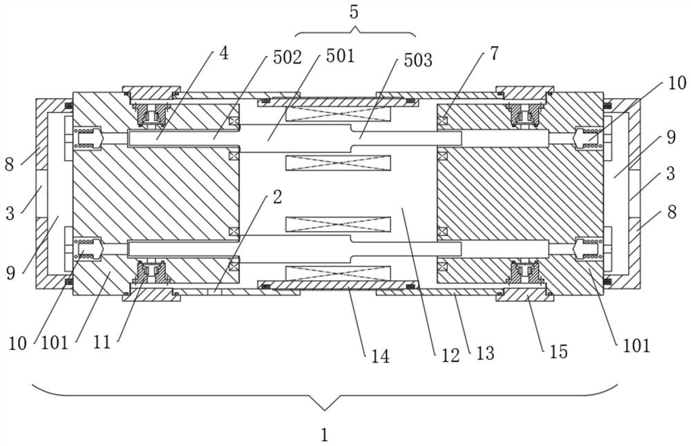
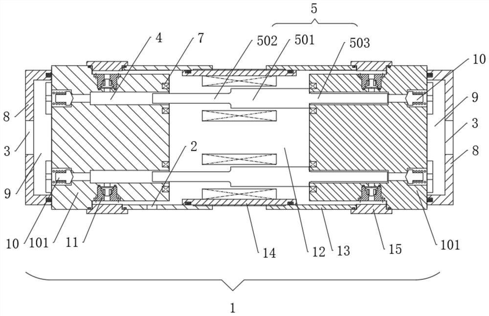
[0032] Such as figure 1 As shown, the deep-sea low-noise variable displacement pump of this embodiment includes a pump body 1, and the pump body 1 includes a cylinder body 101 set at a distance, a first sealing plate 13 extending from the sealing block 101 to the distance, and a cylinder body 101 The plug 15 between the first closing plate 13, the plunger seat 14 sealingly connected between the first closing plates 13 on both sides, the cylinder body 101, the first closing plate 13, the plug 15 and the plunger seat 14 form An oil chamber 12 for containing oil;

[0033] A plunger hole 4 is provided on the inner end surface of the cylinder body 101, the plunger hole 4 is connected with a low-pressure inlet 2, and the outer end surface of the cylinder body 101 is provided with a high-pressure outlet 3;

[0034] A permanent magnet plunger 5 ...


PUM


Abstract

The invention relates to a deep sea low-noise variable pump. The deep sea low-noise variable pump comprises a pump body, the pump body comprises cylinder bodies arranged at intervals, first sealing plates extending from the cylinder bodies to the intervals, plugs located between the cylinder bodies and the first sealing plates, and plunger bases connected between the first sealing plates on the two sides in a sealed mode, and the cylinder bodies, the first sealing plates, the plugs and the plunger bases form an oil cavity used for containing oil; a plunger hole is formed in the inner end faceof each cylinder body and communicates with a low-pressure inlet, and a high-pressure outlet is formed in the outer end face of each cylinder body; and a permanent magnet plunger is arranged in each plunger hole, a groove is formed in the position, close to the corresponding permanent magnet plunger, of the inner end face of each cylinder body, a rotating coil is arranged in each groove, and thrust coils are arranged on the plunger bases. The deep sea low-noise variable pump has the beneficial effects that the purpose of changing the displacement of a plunger pump can be achieved by controlling the movement speed of the permanent magnet plungers, and the stroke of single movement of the plungers can be changed by adjusting the distance between the plunger holes and the plungers so as to change the displacement of the plunger pump.

Description

technical field [0001] The invention relates to the technical field of underwater hydraulics, in particular to a deep-sea low-noise variable displacement pump. Background technique [0002] The development of deep-sea resources has received more and more attention, and the development equipment has become more and more diverse. The hydraulic system has the advantages of strong carrying capacity, high power density, and convenient speed regulation, and is widely used in the development of deep sea resources. However, with the entry of human beings, the noise of various machinery and equipment has a great impact on the life of marine life. [0003] Common pump structures in hydraulic systems include gear pumps, plunger pumps, vane pumps, and screw pumps. The gear pump mainly has the advantages of simple structure, good processing technology, small size, wear resistance, strong anti-pollution ability, etc., but it also has the disadvantages of low volumetric efficiency at low...

Claims


Application Information

Patent Timeline
IPC IPC(8): F04B17/04F04B1/00F04B19/00F04B49/06F04B49/20F04B53/10F04B53/14F04B53/16
CPCF04B17/04F04B19/003F04B1/00F04B53/14F04B49/06F04B49/20F04B53/10F04B53/162
Inventor 胡浩龙龙雷沈雪钱宇羿琦
Owner CHINA SHIP SCIENTIFIC RESEARCH CENTER (THE 702 INSTITUTE OF CHINA SHIPBUILDING INDUSTRY CORPORATION)
Learn More