A stamping die

A stamping die and stamping head technology, applied in forming tools, manufacturing tools, punching tools, etc., can solve the problems of workpiece rotation, workpiece stamping errors, and rough processing surfaces, so as to improve the scope of use, ensure processing accuracy, and ensure no deformation effect

Active Publication Date: 2019-08-27
无锡华光轿车零件有限公司
View PDF6 Cites 0 Cited by
  • Summary
  • Abstract
  • Description
  • Claims
  • Application Information

AI Technical Summary

Problems solved by technology

[0002] When the workpiece is processed, it is necessary to use a stamping die for stamping deformation, and then obtain an effective semi-finished product. In the prior art, when the workpiece is stamped, due to the rapid impact of the punch, the relative displacement between the workpiece and the stamping die will occur, resulting in rough processing surface , the uneven force will cause the workpiece to rotate, resulting in errors in the stamping process of the workpiece, wasting materials and cost, and the punch is located in the middle of the workpiece. Fixed, but still deformed

Method used


Image

  • A stamping die
  • A stamping die
  • A stamping die

Examples


Embodiment Construction

[0023] The following will clearly and completely describe the technical solutions in the embodiments of the present invention with reference to the accompanying drawings in the embodiments of the present invention. Obviously, the described embodiments are only some, not all, embodiments of the present invention. All other embodiments obtained by persons of ordinary skill in the art based on the embodiments of the present invention belong to the protection scope of the present invention.

[0024] According to an embodiment of the present invention, a stamping die is provided.

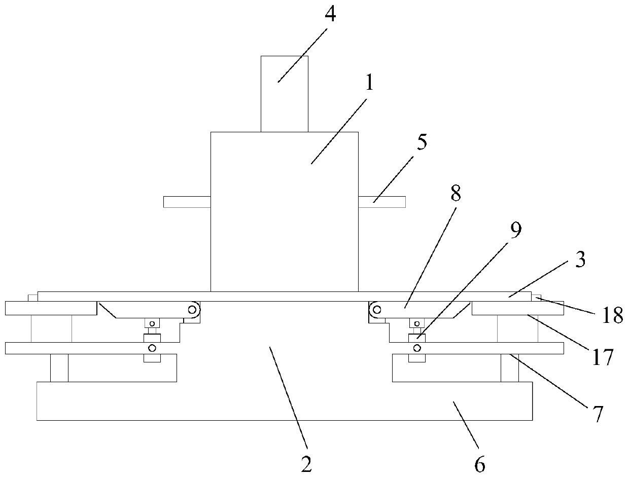
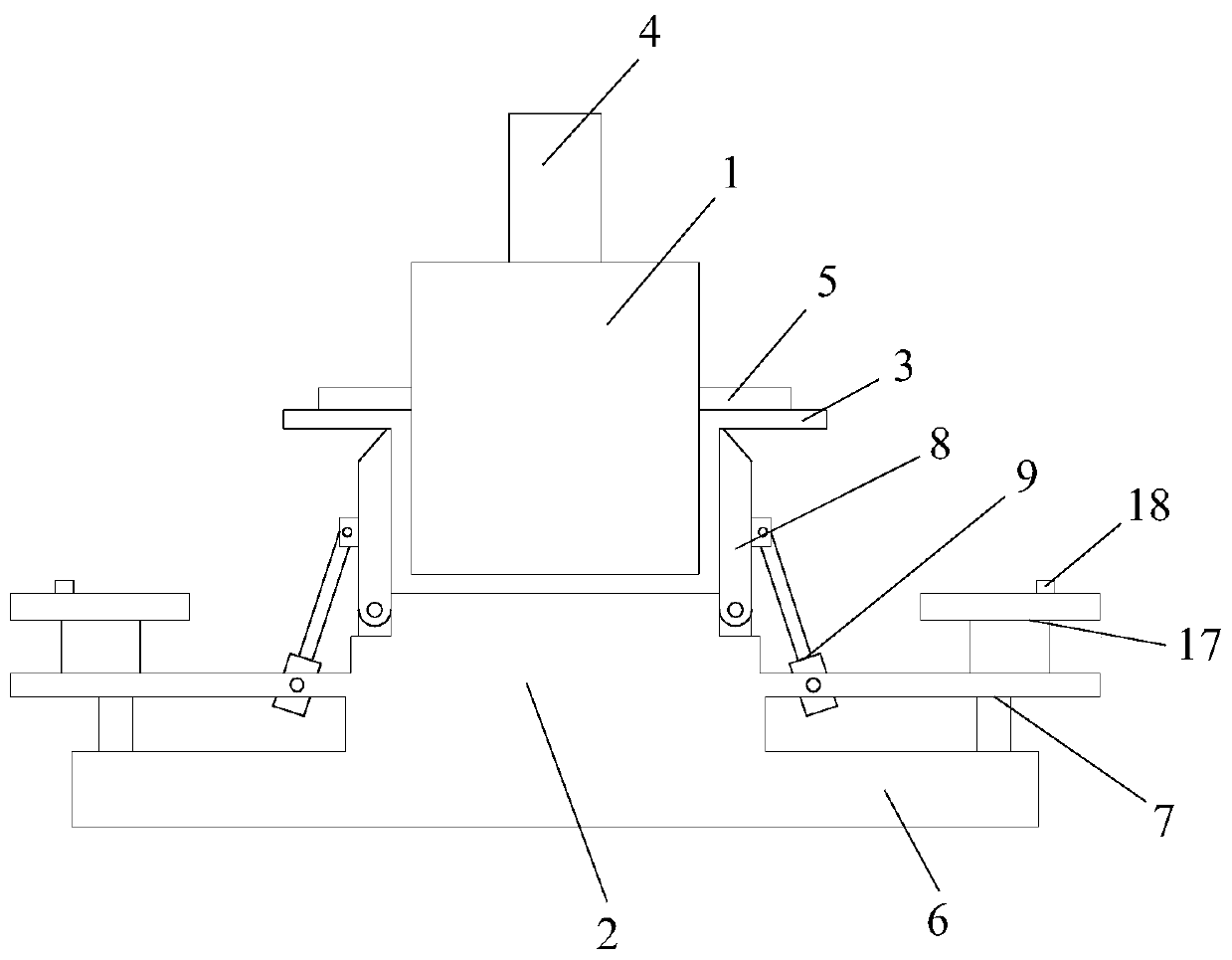
[0025] Such as Figure 1-7 As shown, the stamping die according to the embodiment of the present invention includes a punching head 1 and a backing block 2, the punching head 1 is located above the backing block 2, and between the bottom surface of the punching head 1 and the top surface of the backing block 2 A stamping workpiece 3 is provided, a stamping mechanism 4 is provided on the top surface of t...


PUM


Abstract

The invention discloses a stamping mold. The stamping mold comprises a stamping head and a base plate block; the stamping head is positioned above the base plate block; a stamping work piece is arranged between the bottom surface of the stamping head and the top surface of the base plate block; a stamping mechanism is arranged at the top surface of the stamping head; the two side surfaces of the stamping head are each provided with a movable baffle; the bottom surface of the base plate block is provided with a fixing base; a horizontal bracket is arranged between the top surface of the fixingbase and the side surfaces of the base plate block; the two ends of the top surface of the base plate block are movably connected with movable pressing plates correspondingly; the bottom surfaces of the movable pressing plates are connected with the horizontal bracket through telescopic rods; the two ends of the telescopic rods are movably connected to the bottom surfaces of the movable pressing plates and the horizontal bracket correspondingly; each movable baffle comprises a sliding baffle, a sliding block, a threaded rod and a motor I; each movable pressing plate comprises a fixed plate, amovable plate, a linear groove, a driving sliding rod, a driven sliding rod, a transmission gear and a motor II. The stamping mold disclosed by the invention has the beneficial effects of machining molds which are different in depth, greatly widening the application range, preventing relative displacement in machining and guaranteeing a machined part to be intact, free of scratches and free of deformation.

Description

technical field [0001] The invention relates to the technical field of stamping dies, in particular to a stamping die. Background technique [0002] When the workpiece is processed, it is necessary to use a stamping die for stamping deformation, and then obtain an effective semi-finished product. In the prior art, when the workpiece is stamped, due to the rapid impact of the punch, the relative displacement between the workpiece and the stamping die will occur, resulting in rough processing surface , the uneven force will cause the workpiece to rotate, resulting in errors in the stamping process of the workpiece, wasting materials and cost, and the punch is located in the middle of the workpiece. Fixed, but still deformed. [0003] Aiming at the problems in the related technologies, no effective solution has been proposed yet. Contents of the invention [0004] Aiming at the problems in the related art, the present invention proposes a stamping die to overcome the above-...

Claims


Application Information

Patent Timeline
Patent Type & Authority Patents(China)
IPC IPC(8): B21D37/10B21D28/34B21D43/00
Inventor 张德钢
Owner 无锡华光轿车零件有限公司
Why Eureka
Try Eureka