Special wire fixing frame for combined side surface

A wire-fixing and card-fixing technology, applied in the direction of electrical components, can solve problems such as high technical requirements and lack of any auxiliary tools, so as to achieve the effects of improving safety performance, improving construction quality and progress, and reducing dependence

Active Publication Date: 2021-10-12
CRSC ENG GRP CO LTD
View PDF8 Cites 0 Cited by
  • Summary
  • Abstract
  • Description
  • Claims
  • Application Information

AI Technical Summary

Problems solved by technology

[0002] In the construction of the railway signal room, there are not many auxiliary tools, and most of the construction depends on the technical proficiency of the construction personnel. The cable binding at the base of the solder lug terminal in the traditional way does not have any auxiliary tools. It is necessary to ensure that the wires here are If the cable does not sag, it must be strictly guaranteed that the cables from the soldering lug to the outlet position present a regular pattern. The lengths of the lines on the soldering lugs with the same height must be the same. Here, the wire handle relies on the cable tension on the soldering piece to overcome its own gravity. This requires high technical requirements for the construction personnel to ensure that the wire handle does not deform. Therefore, a special wire fixing frame for the combined side is proposed to solve the above problems.

Method used


Image

  • Special wire fixing frame for combined side surface
  • Special wire fixing frame for combined side surface
  • Special wire fixing frame for combined side surface

Examples


Embodiment 1

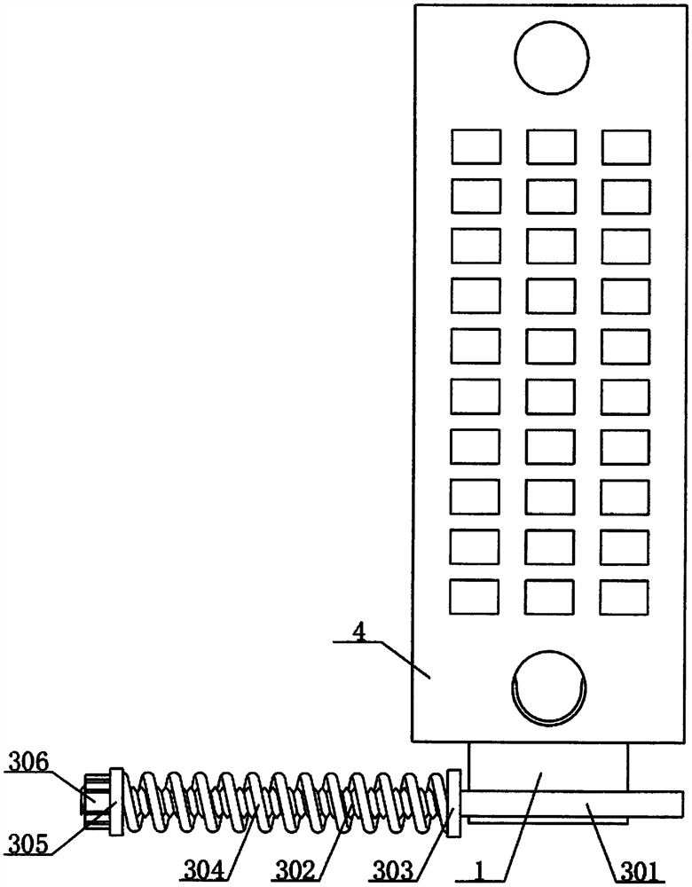
[0020] see figure 1 , figure 2 , image 3 with Figure 4 , the present invention provides a technical solution:

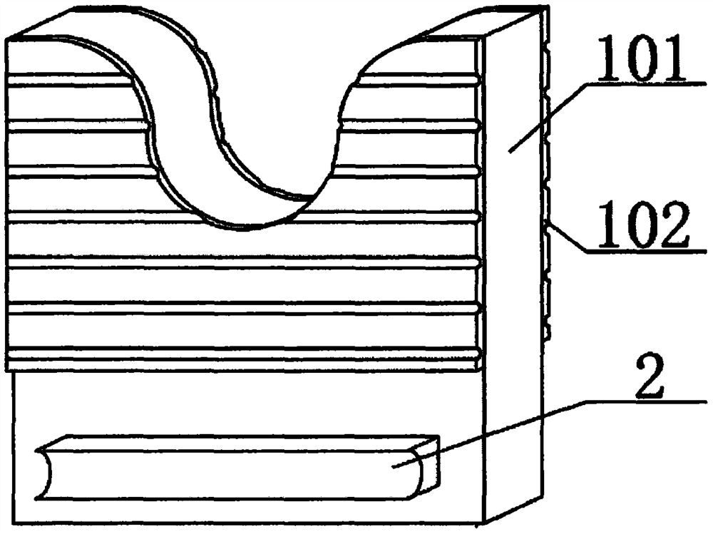
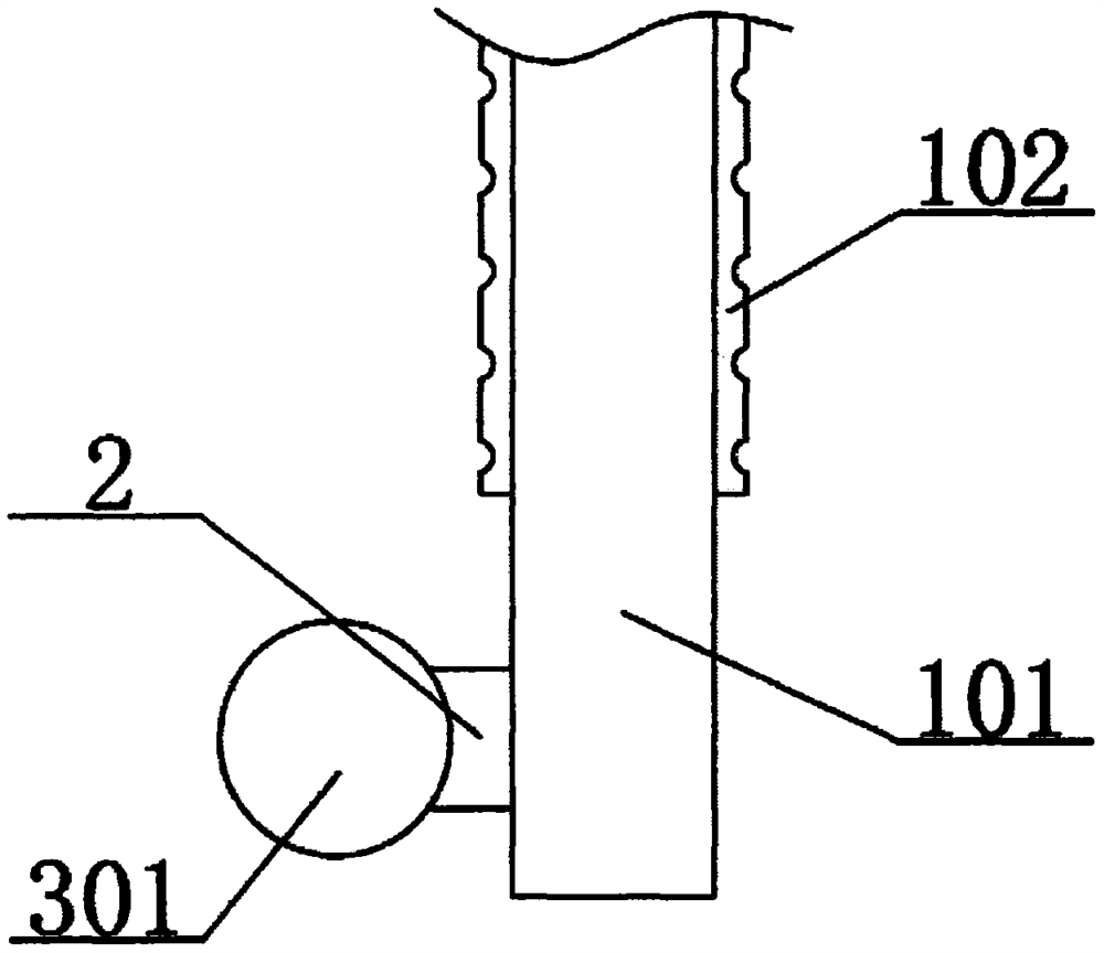
[0021] A wire fixing frame dedicated to combined sides, comprising a fixing device 1, a fixing block 2, a winding device 3 and a lug terminal block 4, the fixing device 1 is arranged on the bottom side of the rear end surface of the lug terminal block 4, and the fixing The device 1 includes a fixed clamping plate 101, a left top plate 103 and a right top plate 104, the bottom side of the front end of the fixed clamping plate 101 in the fixing device 1 is fixedly connected with a fixed block 2, and the outer end surface of the fixed block 2 is fixedly connected with a winding line device3.

[0022] The inner side of the top of the fixed clamping plate 101 is provided with a U-shaped clamping groove, and the U-shaped clamping groove in the fixed clamping plate 101 is aligned with the screw hole on the inner side of the solder lug terminal block 4, so that the fi...

Embodiment 2

[0025] see figure 1 , figure 2 , image 3 with Figure 5 , the present invention provides a technical solution:

[0026] A special wire fixing frame for combined side, a special wire fixing frame for combined side, including a fixing device 1, a fixing block 2, a winding device 3 and a soldering lug terminal block 4, the fixing device 1 is arranged on the soldering lug terminal block 4 The bottom side of the rear end surface of the fixed device 1 includes a fixed clamping plate 101, a left top plate 103 and a right top plate 104. The bottom side of the front end surface of the fixed clamping plate 101 in the fixed device 1 is fixedly connected with a fixed block 2. A winding device 3 is fixedly connected to the outer end surface of the block 2 .

[0027]The inner side of the top of the fixed clamping plate 101 is provided with a U-shaped clamping groove, and the U-shaped clamping groove in the fixed clamping plate 101 is aligned with the screw hole on the inner side of th...


PUM


Abstract

The invention relates to the technical field of railway signal indoor construction, in particular to a special wire fixing frame for a combined side face, which comprises a fixing device, a fixing block, a wire winding device and a soldering lug terminal block, and is characterized in that the fixing device is arranged on the bottom side of the rear end face of the soldering lug terminal block and comprises a fixing clamping plate, a left top plate and a right top plate; a left top plate and a right top plate are arranged on the left side and the right side over the fixing clamping plate correspondingly, first connecting blocks are fixedly connected to the left side of the bottom end face of the left top plate and the right side of the bottom end face of the right top plate correspondingly, and a fixing block is fixedly connected to the bottom side of the front end face of the fixing clamping plate in the fixing device. The outer end face of the fixing block is fixedly connected with a winding device. The fixing device, the fixing block and the winding device are arranged, the fixing clamping plate plays a role in fixing, meanwhile, the support legs provide supporting force for a flexible wire, it is guaranteed that a cable is not deformed after being bound, the use safety performance of the device is improved, the supporting force is provided through the support legs, and the gravity of the wire handle is overcome.

Description

technical field [0001] The invention relates to the technical field of railway signal indoor construction, in particular to a special line fixing frame for combined sides. Background technique [0002] In the construction of the railway signal room, there are not many auxiliary tools, and most of the construction depends on the technical proficiency of the construction personnel. The cable binding at the base of the solder lug terminal in the traditional way does not have any auxiliary tools. It is necessary to ensure that the wires here are If the cable does not sag, it must be strictly guaranteed that the cables from the soldering lug to the outlet position present a regular pattern. The lengths of the lines on the soldering lugs with the same height must be the same. Here, the wire handle relies on the cable tension on the soldering piece to overcome its own gravity. This requires high technical requirements for the construction personnel to ensure that the wire handle do...

Claims


Application Information

Patent Timeline
Patent Type & Authority Applications(China)
IPC IPC(8): H02G3/04
CPCH02G3/0456
Inventor 朱小磊梁海建段丹龙王文宗
Owner CRSC ENG GRP CO LTD
Why Eureka
Try Eureka