
Low-torque-ripple high-efficient permanent magnetic motor stator and rotor structure

A torque pulsation, permanent magnet motor technology, applied in the magnetic circuit shape/style/structure, magnetic circuit rotating parts, magnetic circuit static parts, etc., can solve the inherent performance degradation of the motor, air gap waveform distortion, magnetic leakage and other problems, to achieve the effect of improving efficiency and power density, increasing the width of the yoke, and reducing the eddy current loss and iron loss of the stator.

Active Publication Date: 2015-09-02
苏州德迈科电机技术有限公司
View PDF4 Cites 18 Cited by
  • Summary
  • Abstract
  • Description
  • Claims
  • Application Information

AI Technical Summary

Problems solved by technology

[0003] The built-in V-shaped permanent magnet motor is a common built-in permanent magnet motor. Its working principle is: the rotating magnetic field generated by the electric excitation of the stator winding interacts with the magnetic field generated by the built-in permanent magnet in the rotor to make the rotor rotate; because the permanent magnet Embedded in the rotor, the permanent magnets are surrounded by ferromagnetic materials, which can easily lead to magnetic flux leakage between the poles. When the motor rotates, the air gap waveform will be distorted, and its radial component will cause vibration between the stator and the rotor, and lead to a decline in the inherent performance of the motor.

Method used


Image

  • Low-torque-ripple high-efficient permanent magnetic motor stator and rotor structure
  • Low-torque-ripple high-efficient permanent magnetic motor stator and rotor structure
  • Low-torque-ripple high-efficient permanent magnetic motor stator and rotor structure

Examples


Embodiment Construction

[0020] The present invention will be further elaborated below by specific embodiment:

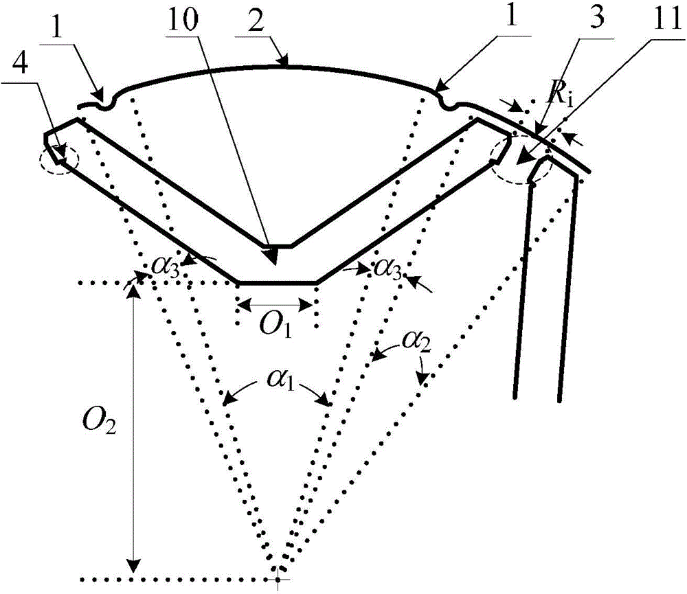
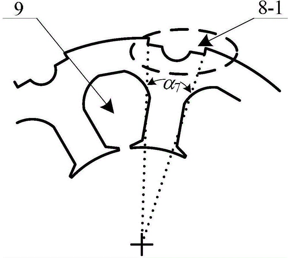
[0021] The invention relates to a stator-rotor structure of a low-torque pulsation high-efficiency permanent magnet motor. The outer circle of the rotor is composed of several four-segment circular arcs connected end to end, and the rotor is provided with a corresponding number of slots for embedding permanent magnets. A number of stator slots 9 are arranged near the stator on the rotor, and stator teeth are formed between every two stator slots. The slot type of the stator slot 9 is a pear-shaped flat-bottomed semi-closed slot. Flatten the bottom of the pear-shaped groove to increase the width of the yoke and reduce hysteresis and eddy current loss.

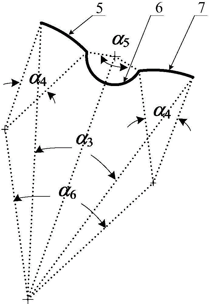
[0022] The four sections of arcs are two sections of the first arc 1 sunken inward, and the angle they occupy on the outer circle of the rotor is α 3 ; A long second arc 2 that protrudes outward, and the angle it occupies on the outer circle...


PUM


Abstract

The invention relates to a low-torque-ripple high-efficient permanent magnetic motor stator and rotor structure comprising a stator and a rotor. The stator employs pear-shaped flat-bottomed grooves. Irregular grooves are disposed on a position, corresponding to the center of a stator tooth portion, on the outer circumference of the stator. A rotor outer circumference is formed by a plurality of four-segment arcs. The rotor is provided with a plurality of grooves in which permanent magnets are embedded. The grooves are flat-bottomed V-shaped grooves. The tops of the left groove and the right groove of each V-shaped groove are provided wedge-shaped grooves for preventing the permanent magnets from moving. The permanent magnets are embedded in the left groove and the right groove. Reinforcing ribs are arranged between the tops of adjacent flat-bottomed V-shaped grooves. Compared with a conventional motor with a built-in V-shaped permanent magnet, the low-torque-ripple high-efficient permanent magnetic motor stator and rotor structure is decreased in permanent magnet magnetic leakage, increased in the utilization rate of the permanent magnets, and provided with a salient pole effect, fully utilizes reluctance torque, improves motor efficiency and power density, improves gap flux density waveform, reduces cogging torque and torque ripple, and effectively reduces core loss and eddy-current loss.

Description

technical field [0001] The invention relates to a stator-rotor structure of a permanent magnet motor, in particular to a permanent magnet motor with a "V"-shaped permanent magnet built into the rotor, which is suitable for applications such as compressors, air conditioners, electric tools and electric vehicles, and belongs to the technical field of motors. Background technique [0002] With the development of rare earth permanent magnet materials, permanent magnet motors are more and more widely used in various fields of national economy. Since the permanent magnet brushless motor has remarkable characteristics such as high efficiency, high power density, and high reliability, and has a variety of structural designs, the optimal design of the permanent magnet motor structure can maximize efficiency and other performance. [0003] The built-in V-shaped permanent magnet motor is a common built-in permanent magnet motor. Its working principle is: the rotating magnetic field gen...

Claims


Application Information

Patent Timeline
Patent Type & Authority Applications(China)
IPC IPC(8): H02K1/16H02K1/27
Inventor 林明耀徐磊
Owner 苏州德迈科电机技术有限公司
Learn More